![]()
![]()
![]()
![]()
![]()
![]()
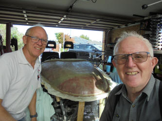
GT40E Build History. ![]()
![]()
![]()
![]()
![]()
![]()
Build History 2
Note the sequence of the build on this web page read from the bottom up. (The most recent evevt is at the top of the page)
From visiting of Roaring Forties in Melbourne, at the F1 that was not (COVID). To the first week of working on the car.
Build History 1 March 2020 too September 2021
Installing batteries, Loads of wiring, Making Dashboard and so much more.
Build History 2 from September 2021 to December 2022
Installing the high voltage wiring, Radio, Making the car have the functions of a modern road car.
Build History 3 from Dec 4 2023
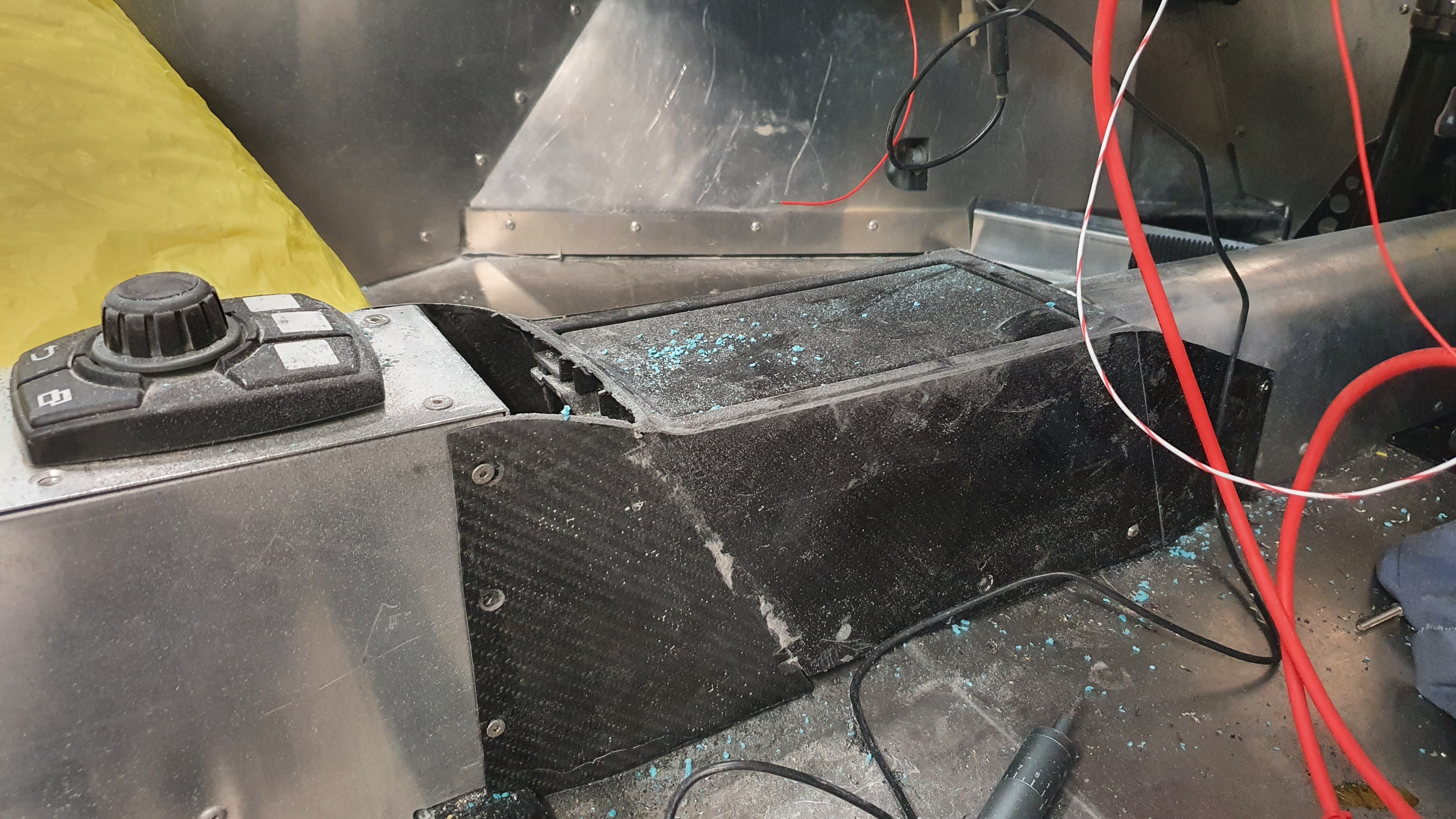
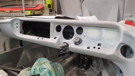
December 30 2022 Week 46. Lower to the ground, Install dashboard, virtually complete battery cooling manifold, Start wiring BMS, Drive shafts received and CV joints ordered.

A month since my last entry, although it feels like little has been done, now
looking back I think I have hade a productive month.
It had been my intention
to lower the car to the ground before the batteries were fitted. This was for
two reasons, that I did not want to have the car hanging with the extra weight
of the batteries and I needed access to the chassis for the block and tackle.
The only problem that I have now is that much of the time I have to work on my
knees.
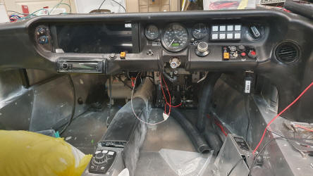
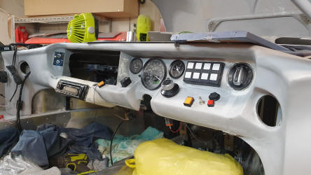
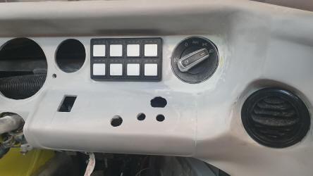
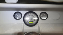
The Dashboard having been received needs the instruments installed,
but prior to this some labels made. These wore made by my regular supplier of
graphic labels Although this did not appear a simple job, due to all the
switches being placed in somewhat random locations it was not easy, and whereas
most companies would tell me to go away Lars did a great job. All the
instruments were fitted, plugged in and pretty much all systems worked first go.
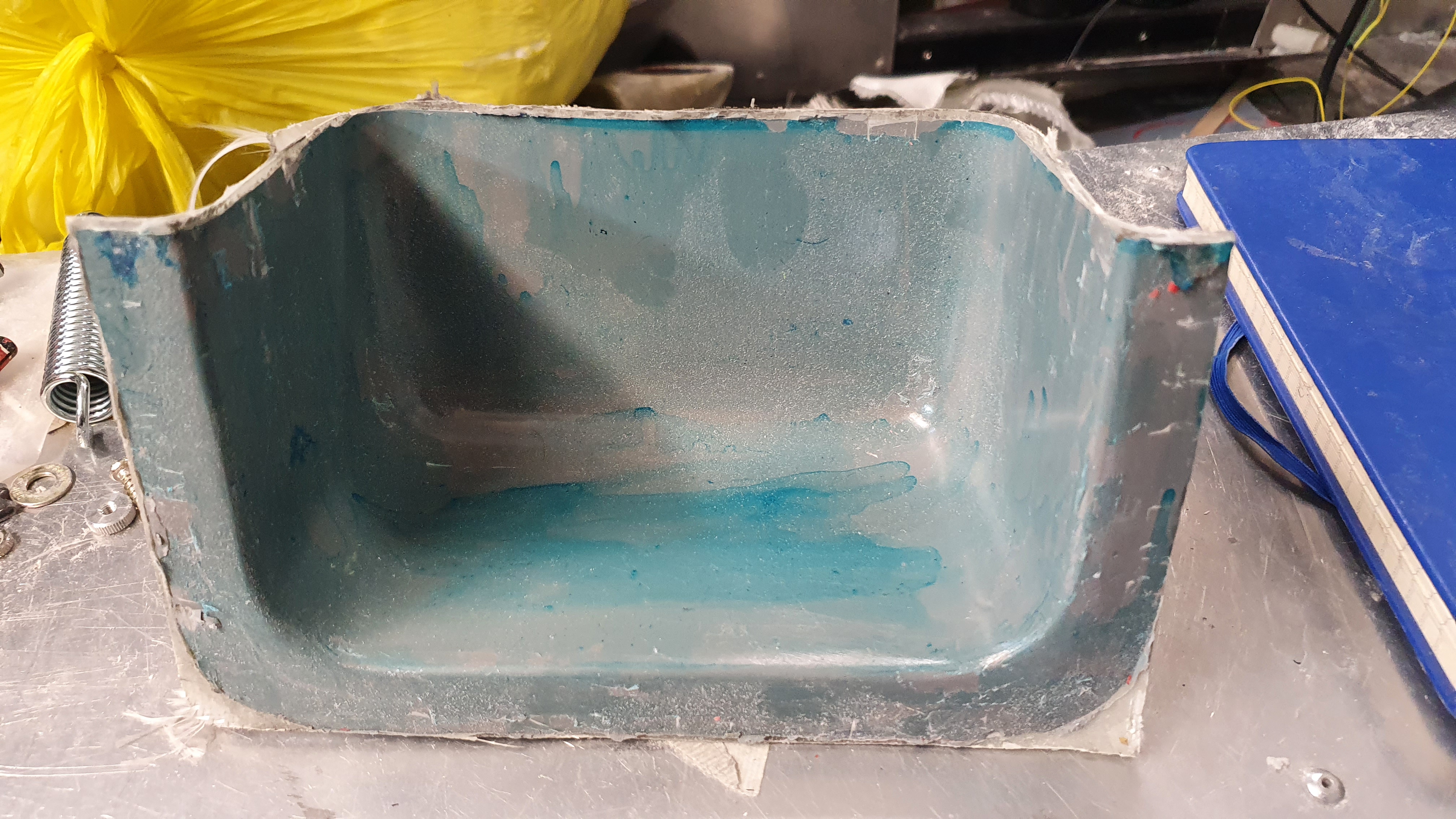
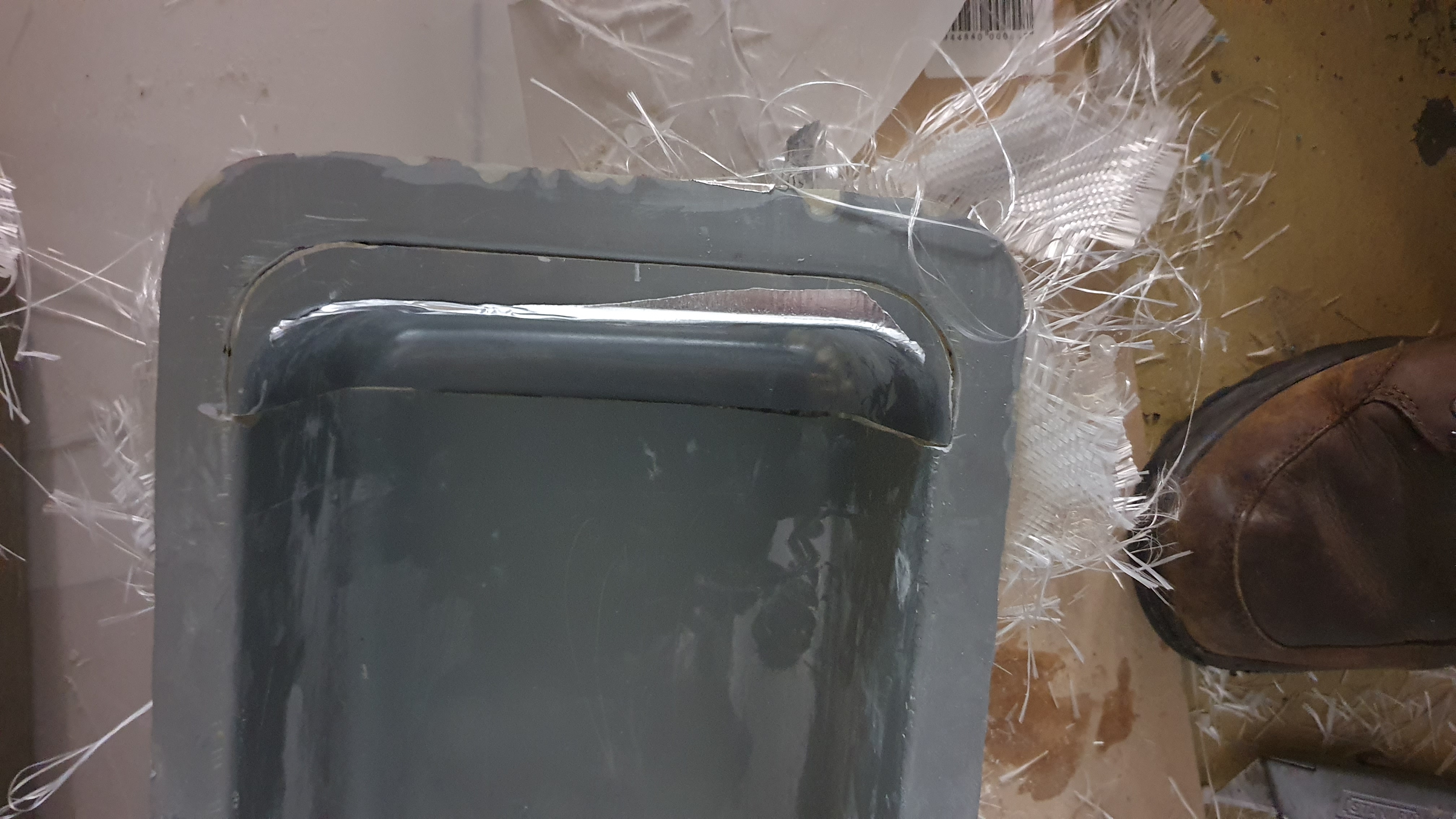
I had been making the Battery cooling manifold, this will sit on the back of the
battery boxes with a fan that will suck air through the batteries if they get
hot. This is now virtually complete.
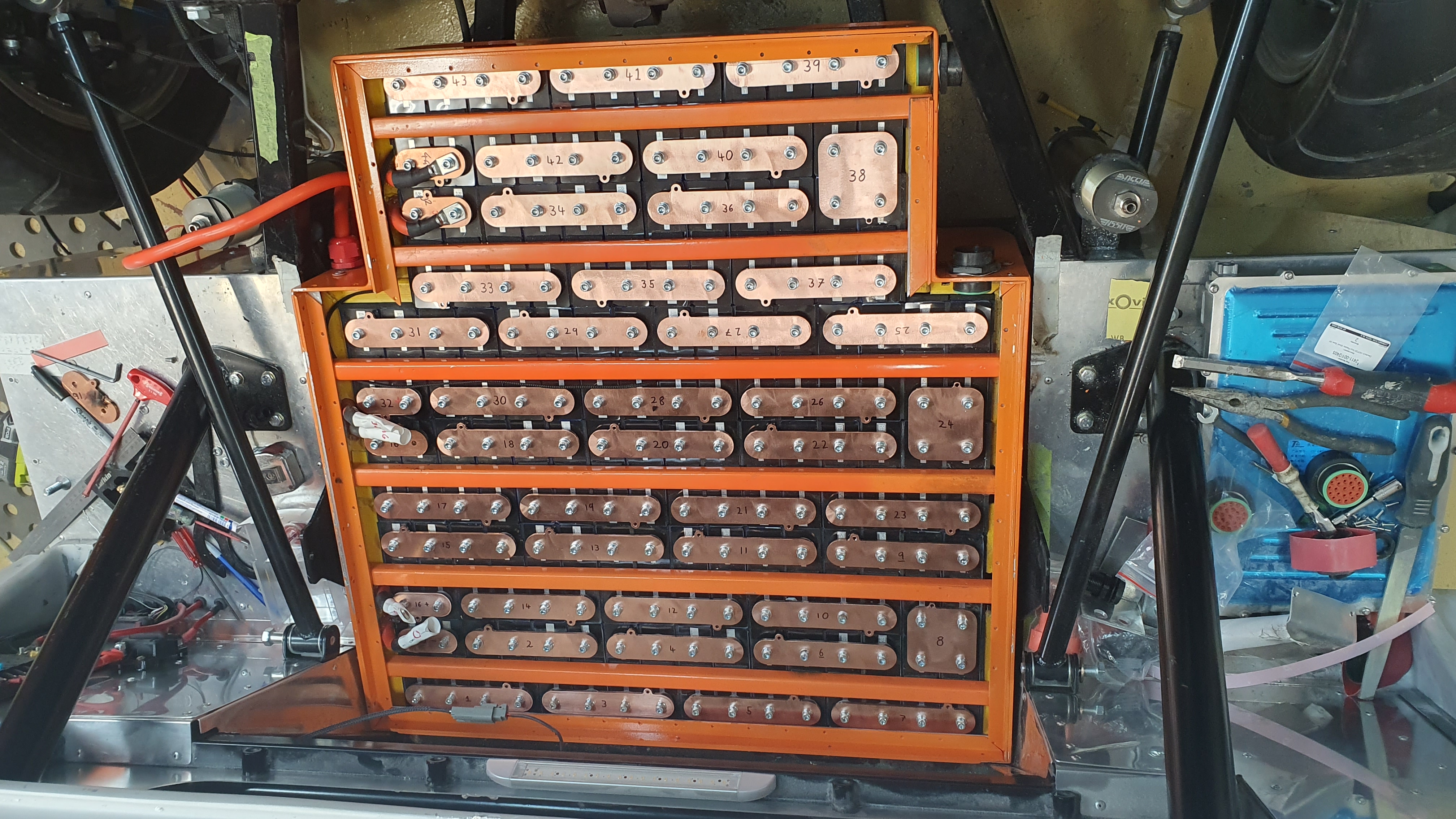
The next major job was to install the
batteries, but here I had an issue. Once the boxes were fitted, quite a long
operation as they had to be precisely located as one of the suspension bolts
holds the top battery in place. About a days job. Once the batteries were fitted
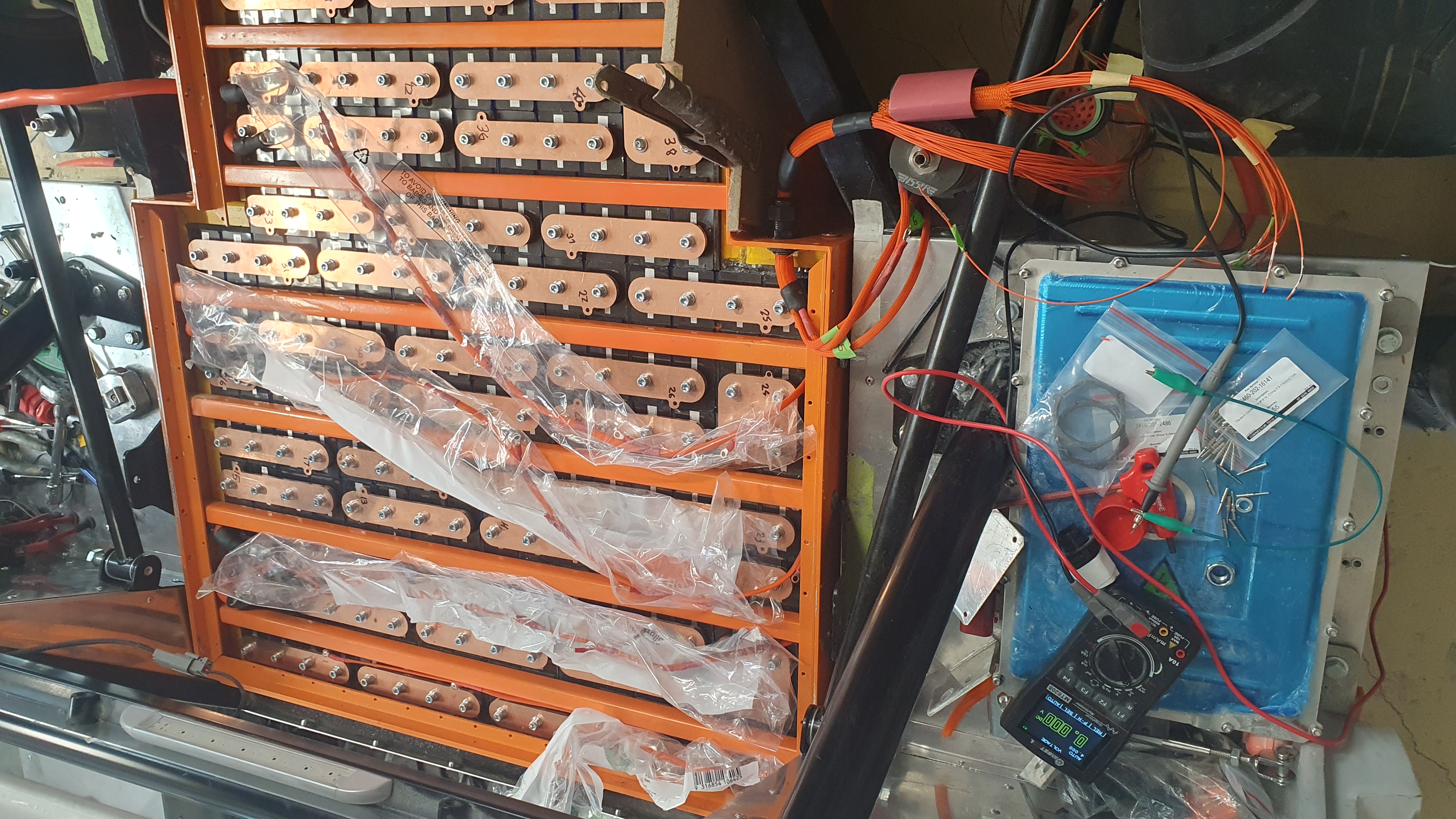
Tim from EV Works checked that all was good to wire the BMS Battery Management
System harness.
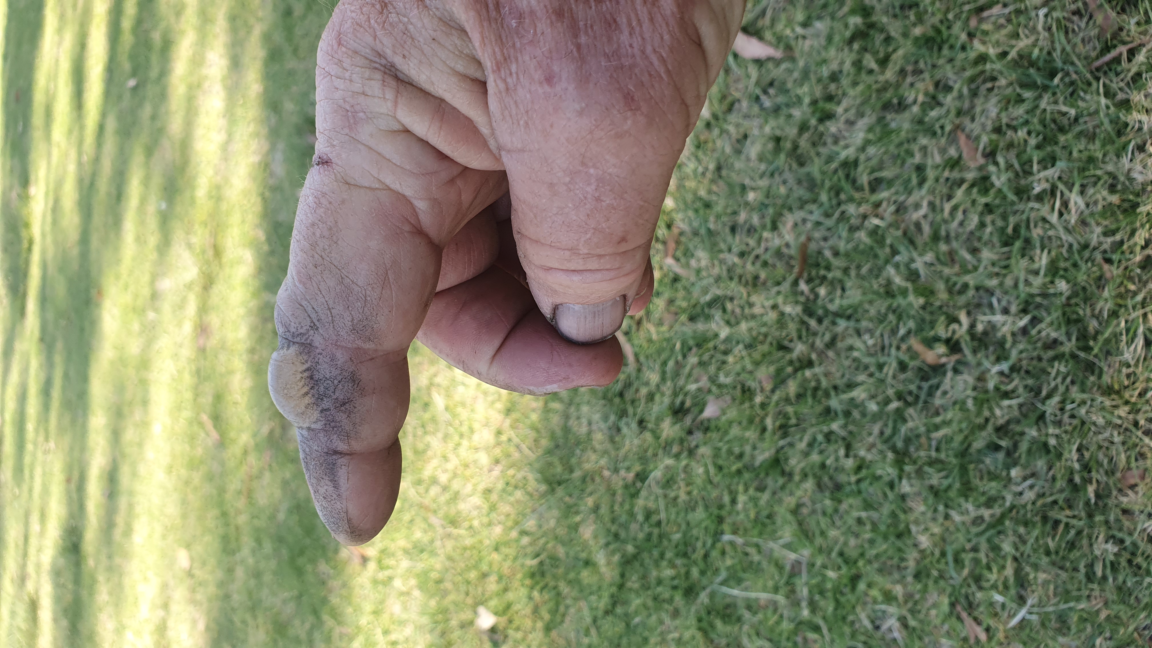
I was being super careful when connecting the wires with the
harness wrapped in polythene sleeves to prevent shorting. when this was half
done I caught one of the wires and promptly about 10 wires burnt, as did my
finger. Equipment to make new fused harness is now ordered. two or three extra
days will be required to make the harness. One other issue I found was that the
two 25 pin plugs exiting the box with the BMS wires were male, live, pins so
this had to be reversed. One final thought on this lesson is to wear fire
protective gloves when working on the high voltage batteries. One little slip
and your hand is by an arc welder.
A nice Christmas present arrived and that
was the two drive shafts 9 months.
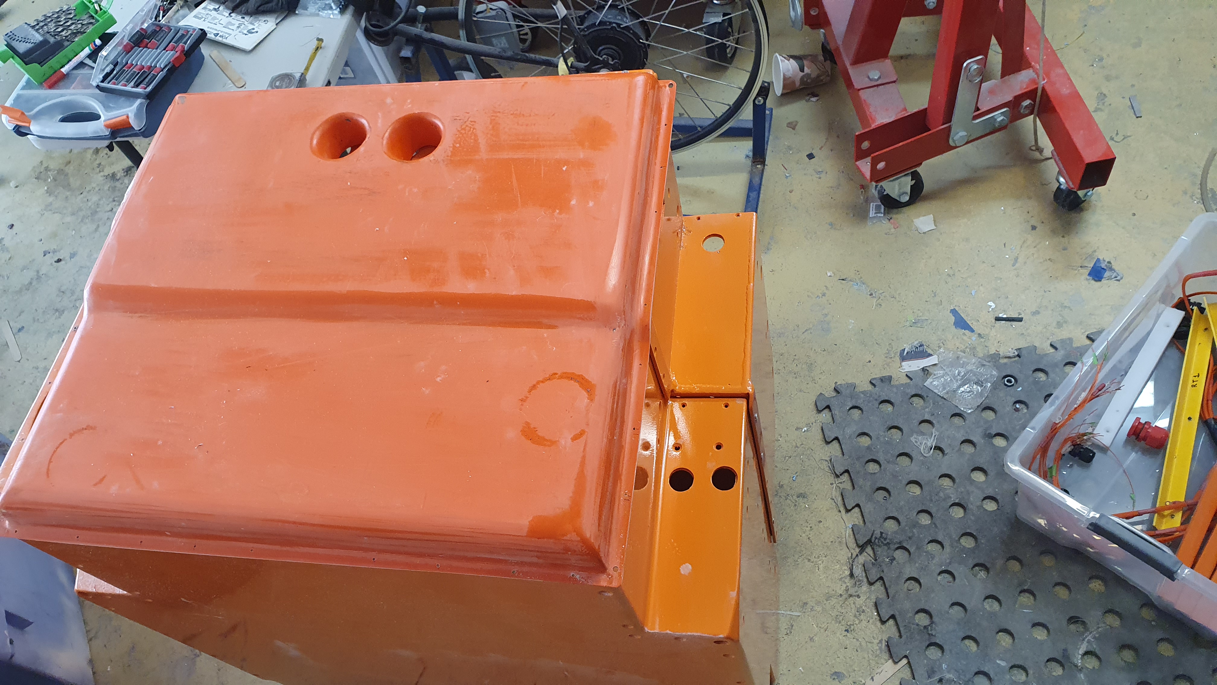
November 27 Week 41. Start making Battery Box cooling manifold, Dashboard received and start to assemble.
.jpg)
.jpg)
.jpg)
.jpg)
.jpg)
.jpg)
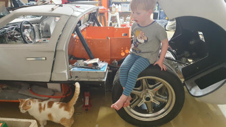
After two months of traveling around Australia, consisting of two weeks at
Burketown flying the Morning Glory Cloud, in my glider, that is now sold.
Arriving home there were a number of items that had arrived for the build,
including The wheels that had Nankang tyres fitted by
Morley Tyre Centre, two battery boxes that my friend Sid had painted, the
dashboard that The Dashboard
Doctor had vinyl covered (they had done a great job and although there was a
bit of a wait, it was no longer than promised, unlike some suppliers who string
out the delivery.) and Linier actuator for the electronic hand break (I had
managed to destroy the previous ones.)
Once I got out or punishment mode (cleaning up emails and the many jobs at home,
I started working on the car.
Laying up the mold for the battery cooling
manifold and starting to make the hardware for the hand break.
Not much done
but at last back on the way.
September 14 Still week 40 of build.
Very little has been
done in recent weeks as I have been more involved in running a charity
PingPongAThon. We raise funds and awareness of slavery around the world. We ran
a Pong in the city of Perth on the 9th and 10th of September and raised over
$11,000 dollars. I consider this a far more important job than building a GT40.
Anyway that is done now and will be followed by me driving to Burketown on the
opposite corner of Australia, over 4,000 k trip. I hope to have a good flight on
the Morning Glory Cloud. (a video can be seen on my Gliding page.)
In the
mean time the GT40 is sleeping with the bonnet and boot lowered, to keep
stresses out.
The wheels arrived a few weeks ago. Only problem now is finding
some tyres to fit!
August 24 Week 40. (although there are more weeks between the 4th and
24th I have been busy working with a charity I support Ping Pong-A-Thon that
fights against slavery. So perhaps only a week working on the car.
Install
wiring loom, Fuse box, Dashboard removed, Battery boxes fine tuned and removed.
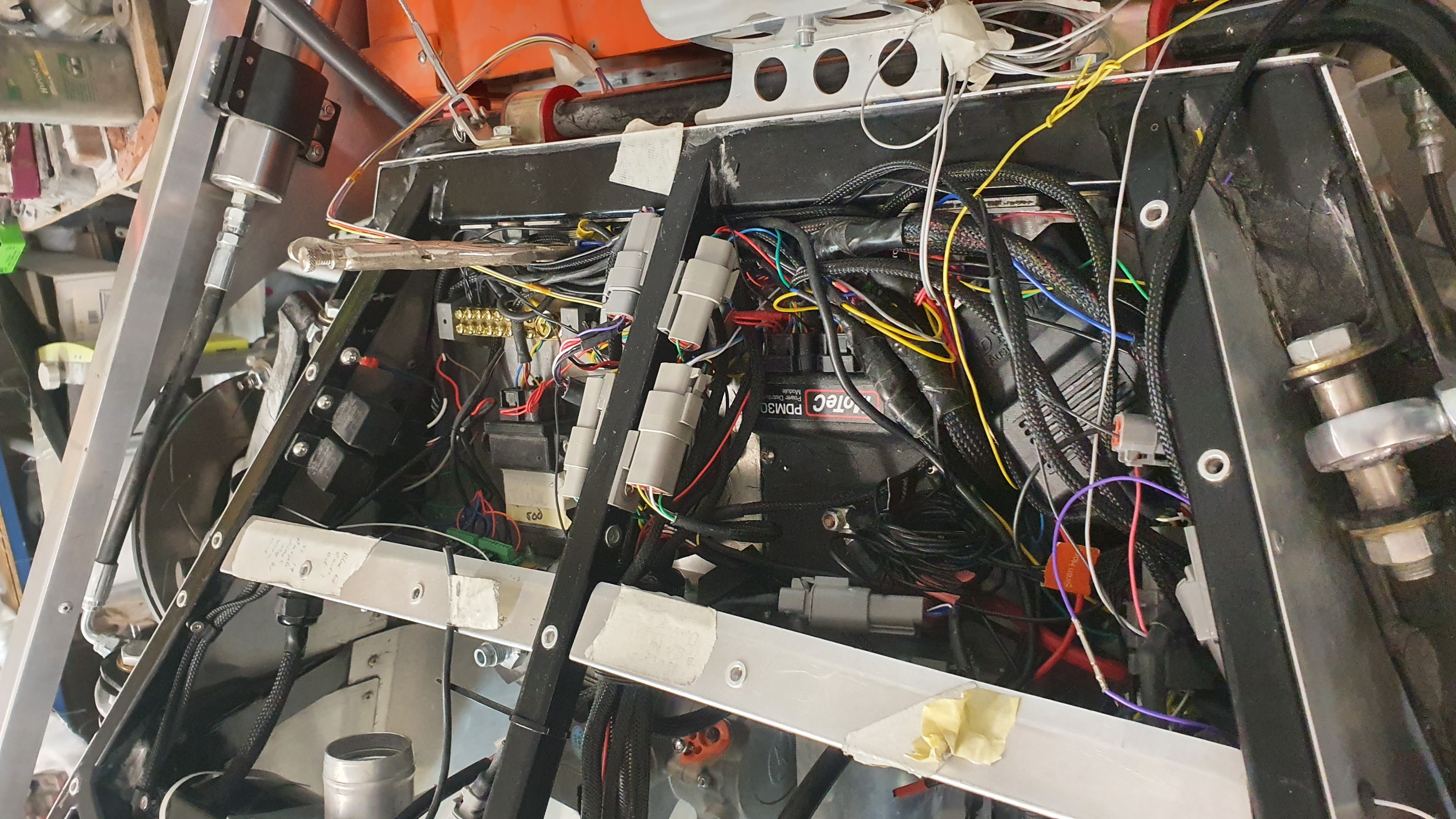
Having braded the wiring loom it was installed back in place, I did find some
areas appeared to shrink once braided and wrapped with shrink wrap, particularly
at T junctions, making it necessary to extend some wires a little.
A rear
fuse box was installed, this had two busses, one permanently on for items like
security system (Dynamco),
parking lights and battery cooling fans. The other side linked to any items that
require the key turned on.
Note that the small monkey wrench is not intended
as a permanent fixture, it is just to clamp the earth wire to earth bus, as I
did not have a big enough crimping tool.
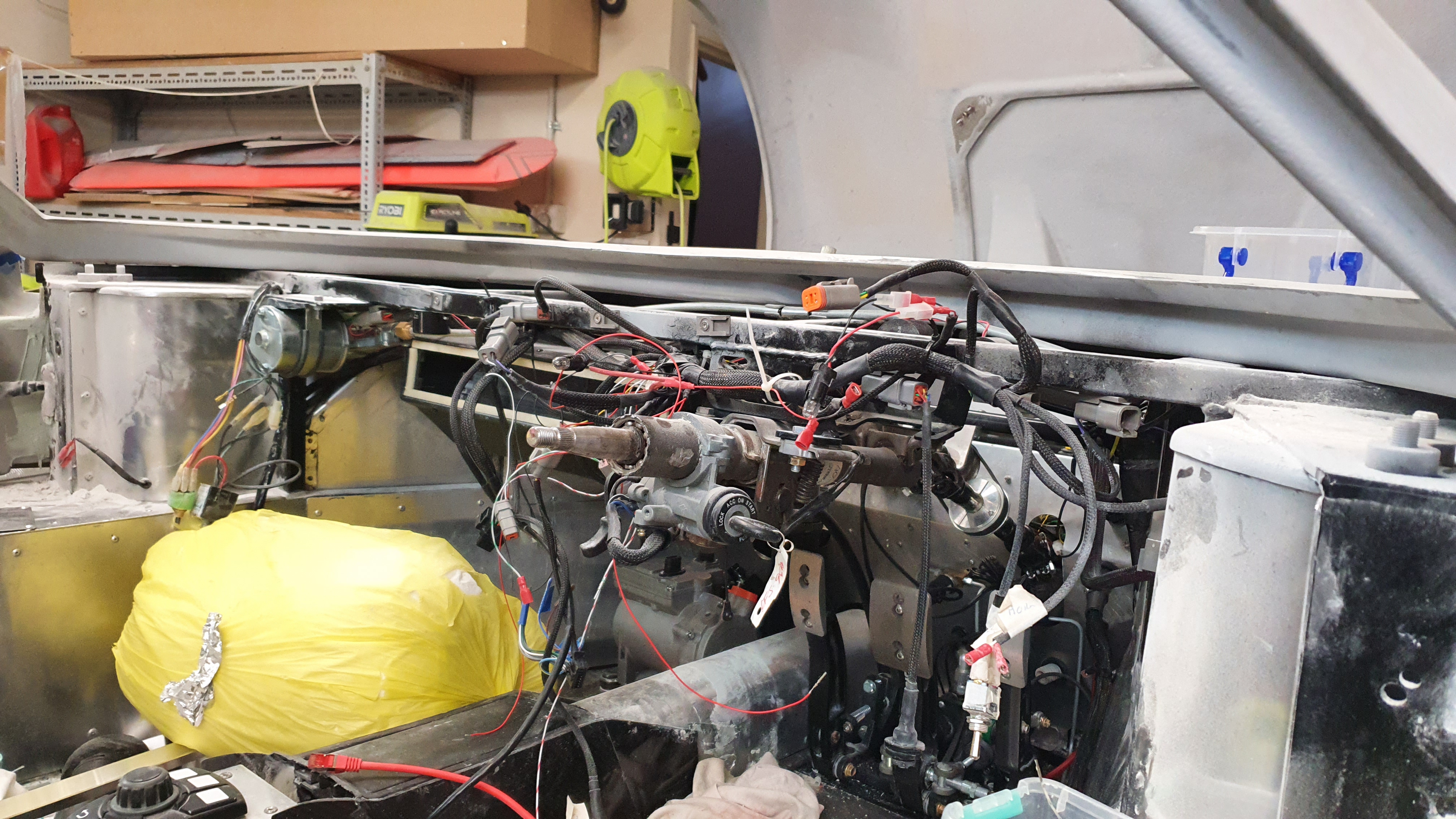
The dash board was removed to send
to the Dash board
doctor in Melbourne, this was finished so there were no lumps and bumps that
may show up once the Vinyl covering is on.
Note on the picture of the car
minus the dashboard has a large yellow bag. This is to rest my head on when
working upside down under the dash.
The rear battery boxes were also finally fine fitted and some plug holes drilled, together with thermostats.
August 4th Week 37 to 39. Continue coffee holder, Parking lights, Modifying Door pockets, Stripped and braided wiring harness, Removed battery boxes.
I have still been working on the coffee holder, but there is still a lot more to
do with it including making some molds and polishing up the carbon finish. More
to follow in later weeks.
I worked out that there would be an issue with
parking lights as the car is wired so that when the key switches off so do all
the systems. So I have added another circuit direct to the battery that will
allow the parking lights to be switched on or off independently of the key.
Diodes were wired in so that there was no possibility of the key or the non key
circuits interfering with each other. Diodes are my friend.
The door pocket
has issues in that it interferes with the door lock, to the right of the pocket
and with the wing mirror plugs. Last weeks photos show how it was shortened. The
depth was reduced by cutting out about 20mm strip and then rejoining back
together. Filling the joints and making them look perfect will be a time
consuming job.
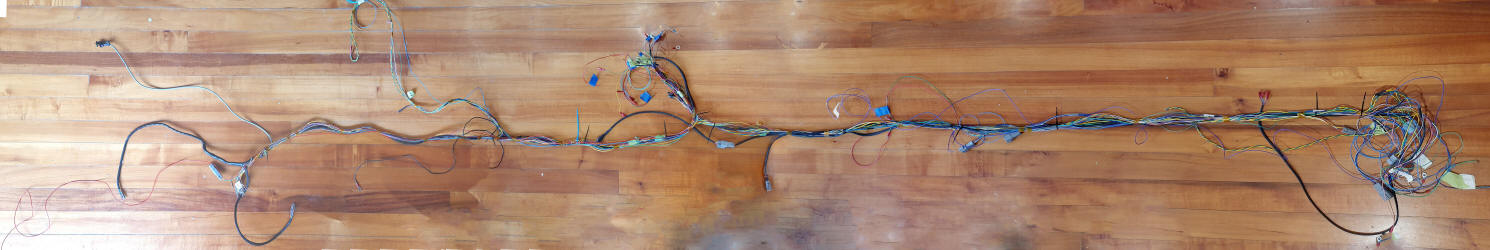
Two other major jobs have started the first almost completed,
that being stripping out the wiring loom between the Tesla in the back and the
electronics in the front, photo above, It has not been braided to look a lot
better. Unfortunately the unbraded photos stitched together well but the braided
would not stitch together. It is now being installed in the car.
The other
job that has been started is the removal of the battery boxes in the back in
preparation for final tweaking and painting.
July 17th Week 34 to 36. A Mile stone passed, Door cable had to modify door, MoTeC training, Electric hand break, Reverse lights installed, Bleeding breaks, Upholsterer came for a look,


I felt that I had reached a milestone at the end of last report, with the vast
bulk of the wiring done. Now it was time to check that all the components were
wired up correctly and the MoTeC programmed correctly. When I first started
programming the MoTeC it was all done in a bit of a rush, jumping into all the
features at once. Because of this I did not fully understood the programming of
the system. There had not been enough repetition of one feature for good
learning, therefor I did not believe that I clearly understood the system,
despite the fact that I am quite happy with computer programming. So I spend a
day with Glen at
Auto Sports Electronics in the corner of his workshop cleaning up the
system, deleting unwanted lines of code and sorting in a respectable order of
functions. After a few hours I was feeling that I better understood the system.
Glen had another go at installing a new actuator for the hand break, but again
we failed with the actuator over stressing its self, despite our best efforts to
set an amp limit when pulling on the break. Another two actuators have been
purchased, and a chat with a contact who understands electronics who may have
some solutions. Let's see if it works in weeks to come.
Once I had wired the
door I found that the cable that enters / enters the door was stopping the door
shutting, a lack of planning or observation there! Rather than a major rewire a
slot was cut in the door frame to allow the cable to pass.
I have started
making a very critical part, not standard in a GT40 but an essential part for a
GT40E, that being the coffee cup holder. I obtained the basic holder from a
scrap yard and am building the surrounds with carbon, that I have laid up in
sheets and cut to shape. Some molds will be made using blue foam. glass and
filler in a few weeks to come.
The doors on the GT40 are quite deep and thus
are large enough for some storage, unlike the rest of the car. An insert is
supplied with the kit, that goes into the door, but unfortunately it impinges
with the door lock system. This has been resolved by me making a mold and copy
of door insert, Then cutting a slot in the insert, so as not to impinge on the
locking mechanism, then filling it with the mold.
The reverse lights were
put in place, they are mini estate lights.
One piece of wiring was completed,
that being the wires to the micro switches that detect if the door is closed or
open. As the information needs to go to both the MoTeC system but also to the
Dynamco security system Diodes were put in line to both the MoTeC and Dynamco
side. I lesson I have learnt where there is any possibility of back feed being
sent to different systems.
I started bleeding the breaks but found a bad
joint at the rear break sensor, requiring me to get a new pipe. After that I had
the same issue with the front sensor, so more pipe made and bent. Let's see if
when I start bleeding again there will be no leeks.
Although it will be some
time before I get the car upholstered I had Tony to come over and look over the
job. Particularly with chain supply issues we ordered the carpet so that
whenever I am ready there will be no delays.
June 25th Week 31 to 33. Wing mirrors working eventually, Inter Door Wiring, Mold finished, Door Locks, Installing Dynamco Security System, Patric's Bonnet, Aircon.


 Many
Months ago, pre COVID, I met an old client of mine, Patrick Brady. He used to
have a business as an auto electrician. He like me is not retired and is making
an electric three wheeler, similar style to the Aerial Atom. I have recently
been helping him make the fiberglass bonnet, photo of the red mold, for his
car. He in the meantime has been giving me advice with the wing mirrors and
hopefully will help with my air-conditioning in the GT40. Patrick's car is fully
air-conditioned.
Many
Months ago, pre COVID, I met an old client of mine, Patrick Brady. He used to
have a business as an auto electrician. He like me is not retired and is making
an electric three wheeler, similar style to the Aerial Atom. I have recently
been helping him make the fiberglass bonnet, photo of the red mold, for his
car. He in the meantime has been giving me advice with the wing mirrors and
hopefully will help with my air-conditioning in the GT40. Patrick's car is fully
air-conditioned.
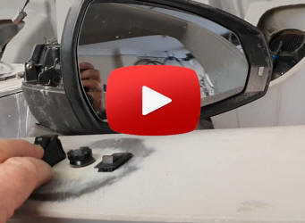
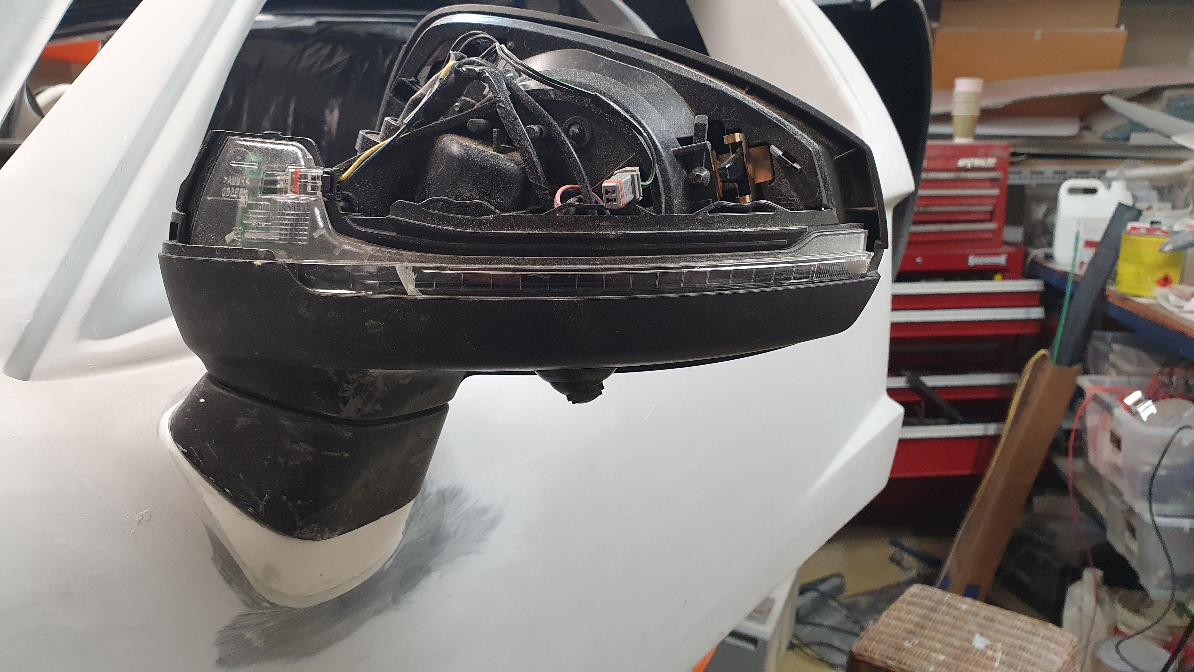
The traumas with the wing mirrors continued, with them
eventually working properly today. I initially had a joy stick, shown on the
picture May 30th, But after a month I could not get it to work, so went to a
simpler joystick. Patrick told me much earlier to use an alternative.
In
addition to items like indicators, heaters and other vehicle proximity warnings.
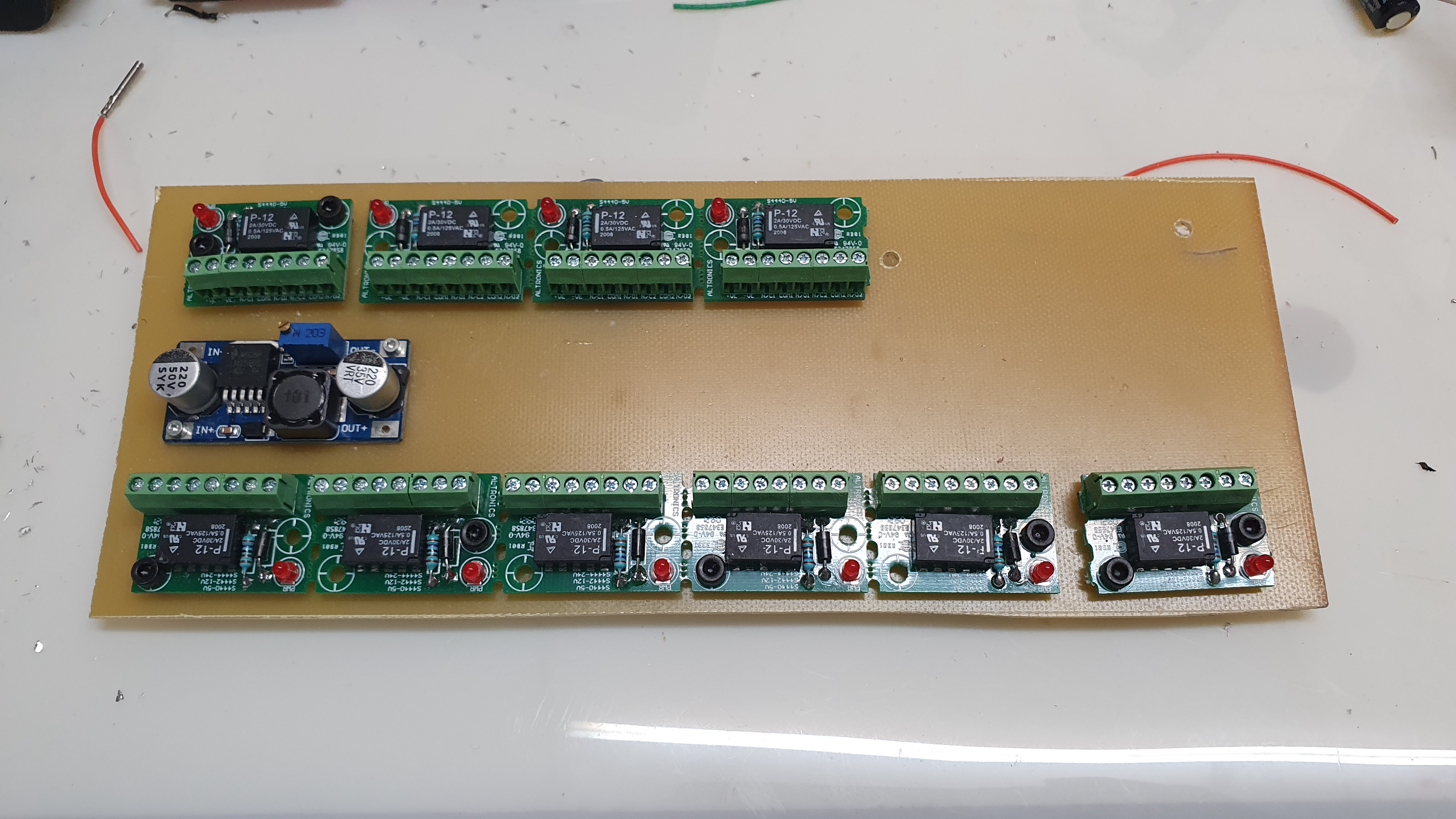
The movement of the mirror is controlled by 10 small relays supplied by
Altronics. 2 control the folding of the mirror after parking the car. The
remaining 8 are set up in 2 banks of 4. Up and Down, Right and Left. The two
banks are Right mirror and Left mirror Alternate relays just reverse the
polarity, So Up is say + - and Down - +. The joy stick controls which of the 4
relays pairs to operate by feeding positive 12v to the relay whilst a separate
switch controls the Left or Right door's mirror by selecting one of two earth
returns.
When first wired up the Altronics relays if I selected one relay,
many others would light up. My thinking was that they were faulty so I made a
new power board with soldered in relays and this worked well as I assembled it
relay by relay until the last two relays were plugged in. Then I got the same
problem. Some thinking was required and my conclusion was that there was some
feedback in the system, So I wired in diodes on all the earth returns and low
and behold it worked, Joy! 5 or more weeks to discover that, Having gone to bed
with a rested mind I came to the conclusion that the Altronics board was more
robust than the power board, who's copper back would fry if there was a short.
So today I rewired the original board putting in the Diodes and it all worked.
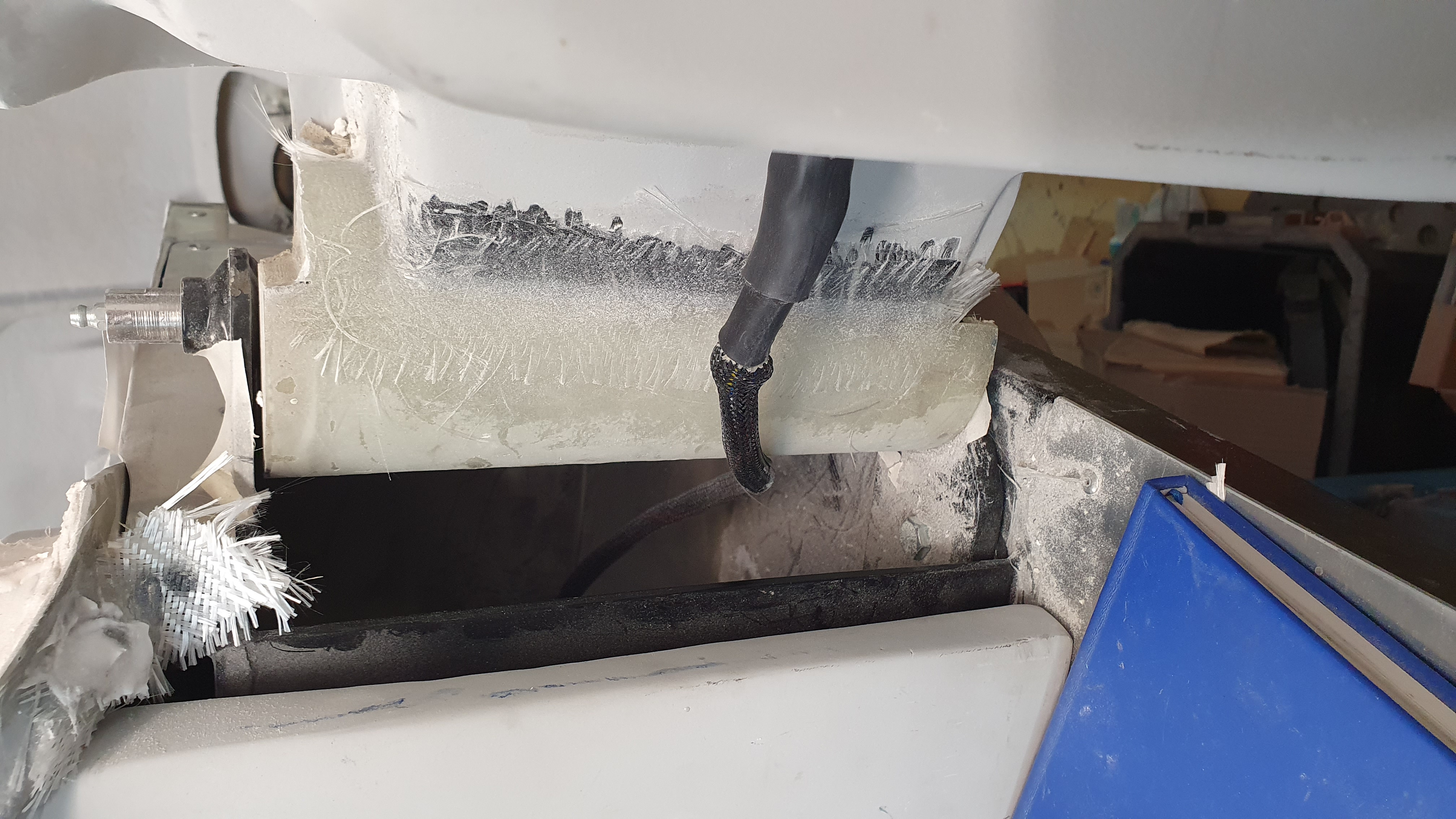
In addition to making the wiring within the right hand door I made a harness
that would connect one door to the other. The right door has all the power
supply and electronics and sends to the left door instructions to power the
mirrors. As the harness has to be flexible as it will bend as the door opens and
closes, it needs to be made to flex. To do this we use a system called,
Concentric Twisting.This can
be seen on HP Academies web site. Photo 3rd from right above.
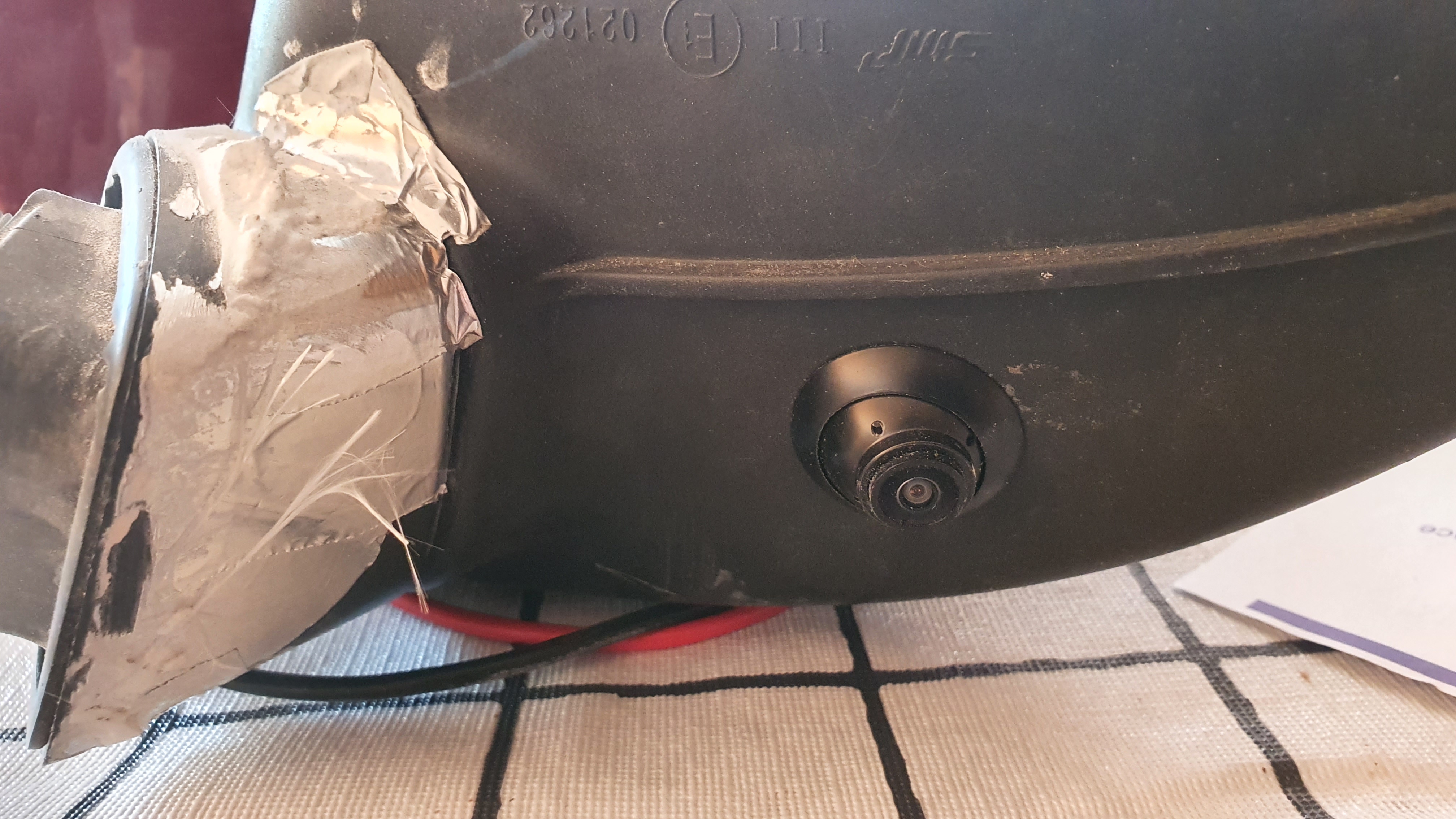
A camera
was fitted to the underside of the wing mirrors, the tape on the photo is just
protecting the mirror whilst the mold is being made.
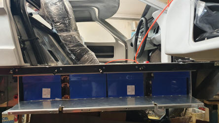
As I am about to start wiring in the security system, the door lock actuators the mechanism has been installed, see photo above 4th from right. The full installation of the security system is due to be the next job, together with AirCon.
Tim came over and fixed the issue we had with the Tesla (Blown fuse on the power board). A great relief to both of us.
May 30. Week 29,30. Blown fuse, Wing mirrors support mold and wiring, Mounted air condenser, Coffee holder, Door storage, fuel filler shaping,

Quite a lot of progress this fortnight. The mental battle
has been trying to get the wing mirrors to work. The issue being that the joy
stick does not have simple wiring. A normally you would hope that you had one
earth return and an up, down, right, left. I will not go into detail but it is
not simple. To get it to work requires two relays to work on series, but there
was too much voltage drop thus stopping both relays working. I am working on
some relays that have minimal voltage drop and can work in series.
I have
also been working on the mounting of the wing mirrors. Naturally the wing mirror
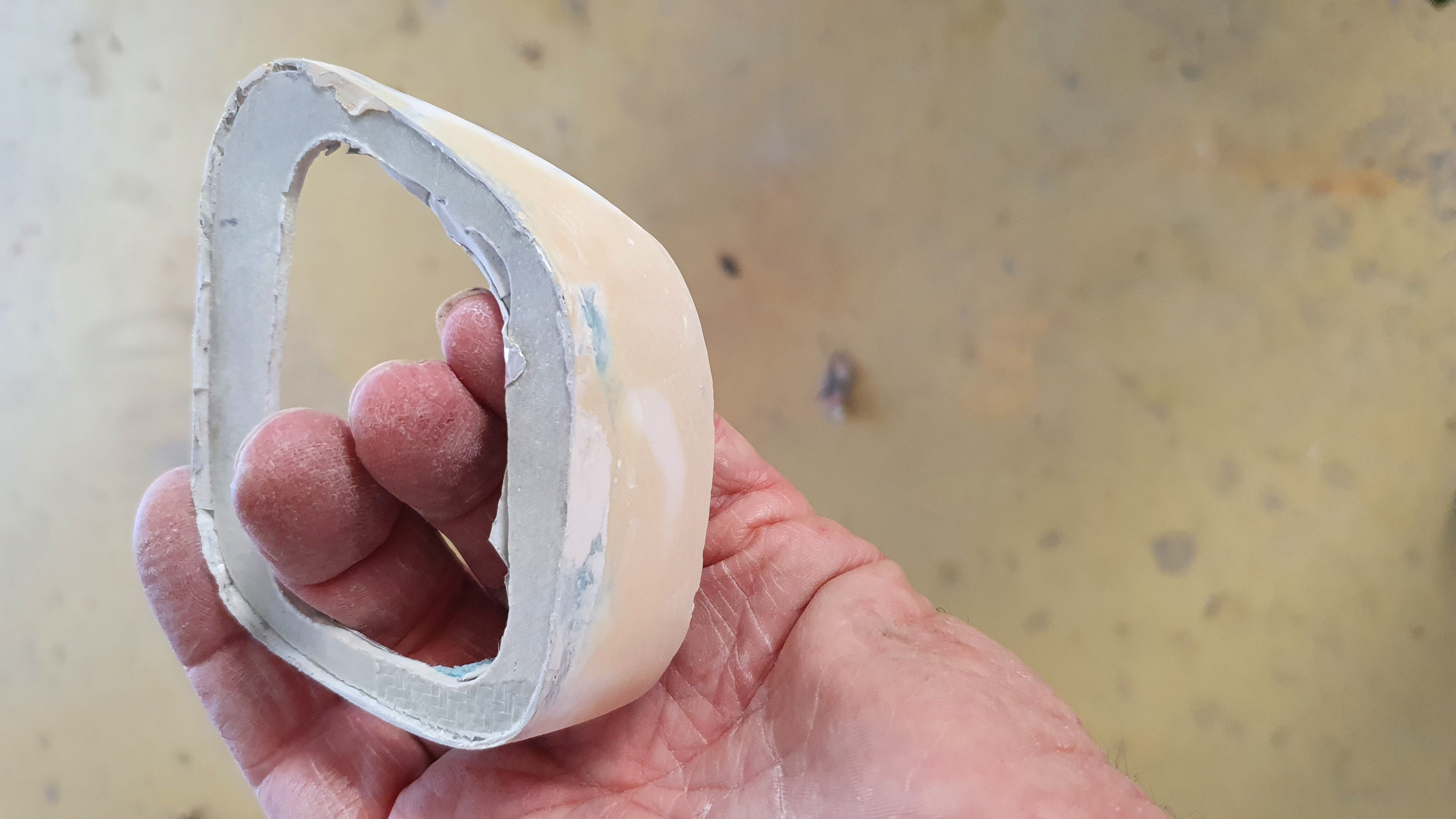
does not fit flush against the door, so I am making a glass fitting that will
give a smooth line between the wing mirror and door. First I mount the mirror on
the door, having wrapped it in silver foil to protect from the resin. Once lined
up I wedge in some blue foam to fill in the gap, then glass around the blue
foam. Once the delicate plug is made, clean it up and then make the female mold.
The final product will be made next week
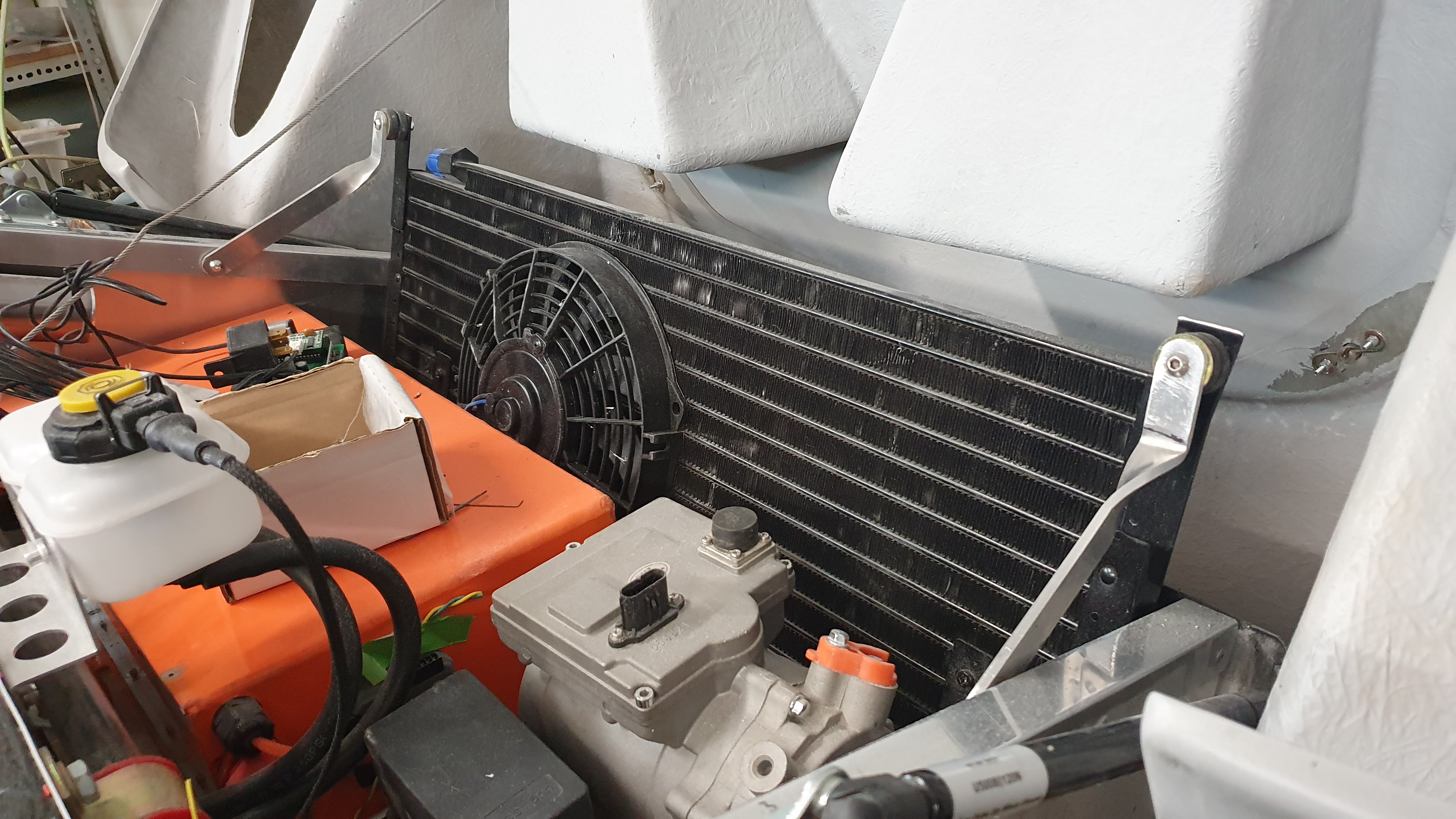
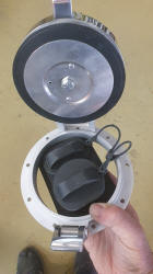
I had time to mount the
air-conditioning Condenser in the front of the car.
The ability to have a
coffee when you drive is vital, so I found a coffee cup holder at a local scrap
yard and I am making a carbon fiber surround that I hope will look good.
When
making items with glass and carbon it is a good idea to continue with a number
of projects, as the resin mix can do the many jobs at once. The other glass
project is resolving an issue with the storage containers that are mounted in
the doors. They give me an issue in that they impinge on the door locking
system, so I am going to shorten them a little, the first job is to make a mold
of the end of the culprit and later cut it into the original part.
The other
bit of glass work is shaping the bonnet where the right hand fuel filler has
been removed. It is quite difficult to see that I get an aesthetic shape of this
complex curve, get it wrong it could spoil the car.
May 15. Week 27, 28. MoTeC programing, Hand Break, Tesla not working, Starting Wing Mirrors


.JPG) Another
Two weeks have passed and may more hours as usual. I fitted the hand break with
the cable arriving from
FlexibleDrive. Who did a great job making the cables to size. We set up the
MoTeC to pull the cable until a low ampage was reached. However my cheap
American actuator, that was sold as a hand break actuator, pulled its self to
pieces in its first attempt. I have been using linier actuators fromMotion Dynamicsin the past for all sorts of uses. So one has been ordered and the previous
actuator put in the bin. When I get that working I will post a video. Let's hope
it works.
Another
Two weeks have passed and may more hours as usual. I fitted the hand break with
the cable arriving from
FlexibleDrive. Who did a great job making the cables to size. We set up the
MoTeC to pull the cable until a low ampage was reached. However my cheap
American actuator, that was sold as a hand break actuator, pulled its self to
pieces in its first attempt. I have been using linier actuators fromMotion Dynamicsin the past for all sorts of uses. So one has been ordered and the previous
actuator put in the bin. When I get that working I will post a video. Let's hope
it works.
With the bulk of the wiring completed, Oh I still have the wing
mirrors to do, I have been checking out the programming of the MoTeC and
testing, with much help from Glen. You will see a little video of a typical
instance with the indicator well on the way to working. You need to be aware
that the self canceling stalk operated system will not fit in the GT40, and
having experience with toggle switched indicators in a MK I sprite. I found that
they were often left on, flashing as I merrily drive straight with an indicator
flashing. So the MoTeC's ability to sing and dance was bought into action. The
indicator has flashing buttons on the dash and behind the dash small
programmable buzzer. I have four behind the dash, one for the indicators and
three more that will be programed to suit the warning they will transmit. These
can be obtained off eBay "Programmable warning buzzer". I have not set up the
steering angle sensor that will work the self canceling of the indicators. I
have also programed them to switch off after 3 minutes of flashing.
Two
repairs. The light switch had an issue that when I selected O the Drive lights
came on, and the two LED's in the hand break selector I burnt out. So both
devices needed rearing or modifying.
Tim came over to start to get the Tesla
working, but no joy, may be this week.
I said that the bulk of the wiring was
done, but the wing mirrors are yet to be installed. There are about 20 wires to
come into the doors! The list of things a wing mirror has to do if you use a
modern one.
Mirror Up, Down, Left, Right, Fold, (Each requires two wires and
information to be sent from the joy stick to the opposite door.) Indicator,
Demister, Proximity warning. Door open light, The GT40 also has a large storage
area that will need a light. That is about 16 cables and I think there will be
more. I have a nice little joy stick, for the mirrors, that has about 10
connection pins. I needed to test each combination to work out which pair send
the message for only one function e.g. Left mirror UP. That took some time. I am
now building the board that contains a number of mini solenoids to do the job.
Let's see if I can get it working.
April 30 Week 23 - 26
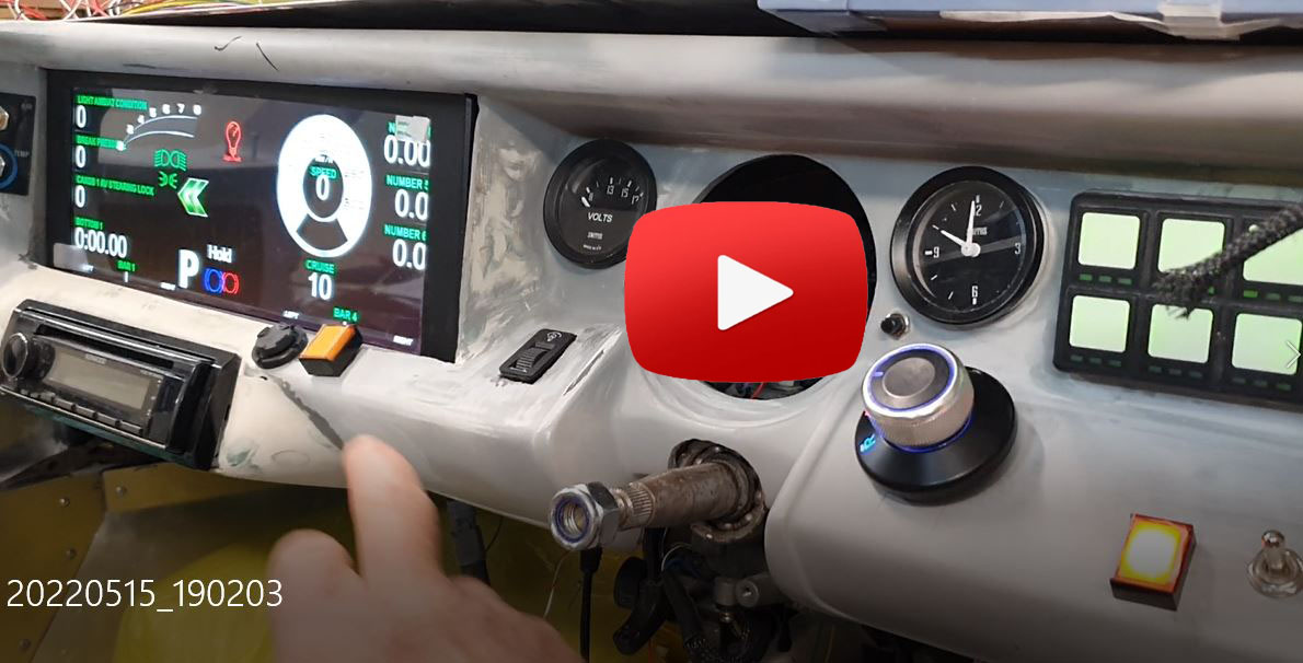
COVID Lockdown, Wiring, Wiring, Wiring, Headlights, Rear View Mirror, Wiper Motor and Air Con. Trying to get the MoTeC to work. Hand Break Cable.


As we had been in contact with our two grandsons age 3 and 6 months, who had
COVID, we had to go into lockdown. This gave me more time to work on the car.
Still wiring, wiring and more wiring. To give you an idea it took me all day to
wire the map lights in the rear view mirror and the boot light. There were many
holes drilled into the body to find a root for the power to reach to the lights
and these are in the process of being glassed over then filled. I may be slow,
but I have no instructions to follow as much of what I am doing is not standard.
I also installed the front headlights. These are Hylux lights and they JUST fit,
in the height dimension. One thing with the Hylux is that the beam adjustment is
done by turning screws that are located on the front of the lamp. Of course the
GT40 I have to adjust from the rear. So the two springs that pull the light in
place allowing flexibility of movement when lining up the lights have been
changed to push springs. The springs are not in place yet. I will wait for all
of that once the car is on the ground and I have some basic idea where they need
to move to.
In addition to the headlights I am well on the way to installing
the turning lights. These light up when the car makes a tight turn to the right
or left. There is a suggestion that I made to Lexus to improve their car, but
they were not interested, so my GT40 will have that feature. You will see at the
end of the build.
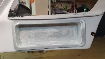
There are two fuel filling points on the right and left of
the car, at the back of the bonnet. Obviously I will only have one filling point
for electricity, so the drivers side hole is being filled with many layers of
glass. To fill the hole I chamfered the edge of the hole on the top and
bottom. I then layer up one piece of woven glass to the underside, nice and
tight, noting not to use resin on other than the edges. Once the resin had
hardened I put resin on the rest of the glass. I then worked on the top, laying
down about 6 - 8 layers of glass, then sanding down the edges. The following
day, once the resin had been hardened, another 6-8 layers of glass
followed by sanding level, followed by a couple of weeks at the Phisyo to get my
shoulder fixed.
I also installed the windscreen wiper motor, only to find
that the air-conditioning unit needed to be lowered, so off to CadCut to have a
new mounting bracket.
At last it was time to fire up the MoTeC to see if the
switches would control the lights. Unfortunately not, so Glen from
Auto Sports Electronics came over for a day to check things out. After a day
of tracking things down we were no better off, but I am sure that we will get
there. It appears that there is a problem with the CANBus, but let's see.
One
other development, I collected the hand break cable, that will link to the
electrical actuator. That will be fun programming.
April 3 Week 20 to 22
Still more wiring, Steering sensor, Windscreen motor, Mirror & Fiat 500 technology. Unwanted visitors.

 The
wiring continues With many hours of work, pretty much under the dash board,
however about a week ago I reached a point where I could braid the wires. This
entailed disconnecting many of the connections, taping them with a note of their
original connection point and then braiding the loom. Then of course
reconnect all the wires back into place. The next job, once the front lights are
wired will be to start testing all of the connections. The last 3 weeks felt as
if there was little progress being achieved but in reality wiring does not show
up as a big step forward.
The
wiring continues With many hours of work, pretty much under the dash board,
however about a week ago I reached a point where I could braid the wires. This
entailed disconnecting many of the connections, taping them with a note of their
original connection point and then braiding the loom. Then of course
reconnect all the wires back into place. The next job, once the front lights are
wired will be to start testing all of the connections. The last 3 weeks felt as
if there was little progress being achieved but in reality wiring does not show
up as a big step forward.
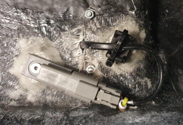
The MoTeC steering angle sensor was installed and
wired in place with the break pressure sensors, see photo.
There were two
items that were installed on Saturday that made me feel as if I made a couple of
leaps forward. These being the windscreen wiper motor, that took a bit of
juggling about, with the wire harness blocking access. Yes I know it would have
been better to have fitted it first but the parts took some time to arrive.
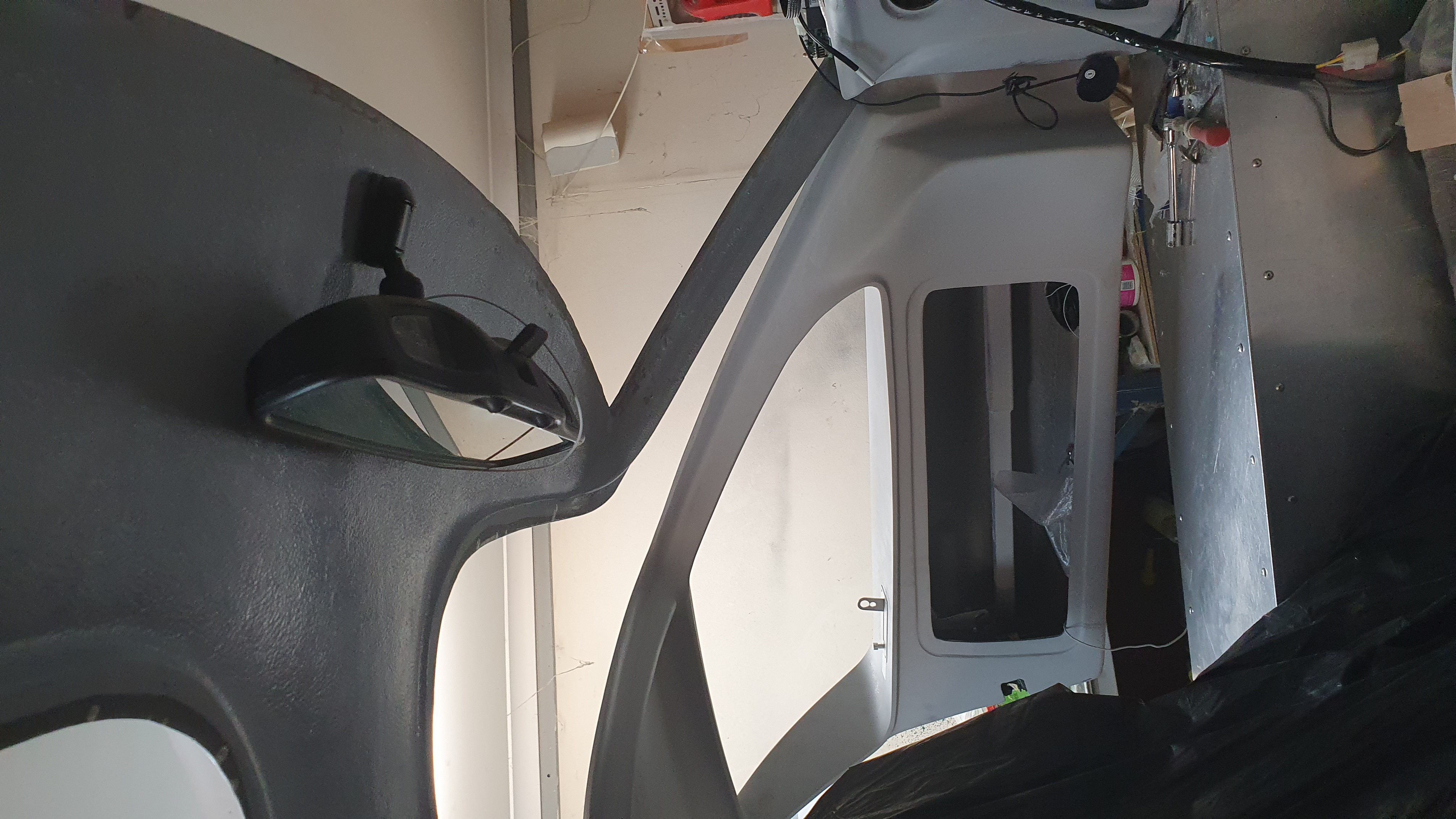
The other item fitted was the rear view mirror. I had a dilemma in that fitting
interior lights in such a small cabin was not going to be easy. The first car
that resolved this issue by installing the lights as part of the rear view
mirror was the original Fiat 500. I obtained my mirror on EBay as a Mustang
mirror.
When I work in the garage I usually have the door open not only to
cool the environment but also to allow passing friends and visitors to have a
chat. Last week I was working with my back to the door I herd a noise, on
turning around I saw someone taking my mountain bike. I was too slow to get
round the car and stop him. Anyway got some photos.
March 10 Week 19
Wiring, Wiring, Wiring and fitting the radio.
 I
have continued the last few weeks wiring the car, and this was only dash board.
This may seam not a lot but I have found that a day is put aside to wire up a
load of instruments only to find a couple are completed and not even tested.
However it is looking as if the dash will be wired up by the end of next week.
The next job will be to wire the outputs i.e. front lights, controls to the
motor and then Test. Once completed and tested it will all come out and be
wrapped into a harness.
I
have continued the last few weeks wiring the car, and this was only dash board.
This may seam not a lot but I have found that a day is put aside to wire up a
load of instruments only to find a couple are completed and not even tested.
However it is looking as if the dash will be wired up by the end of next week.
The next job will be to wire the outputs i.e. front lights, controls to the
motor and then Test. Once completed and tested it will all come out and be
wrapped into a harness.
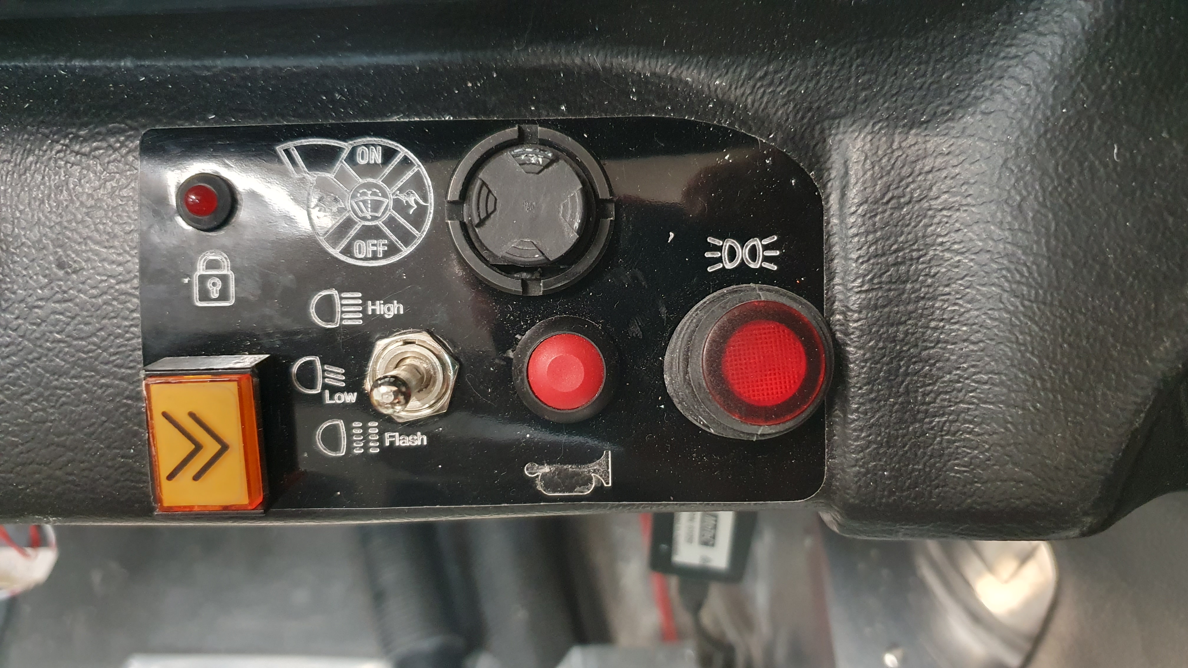
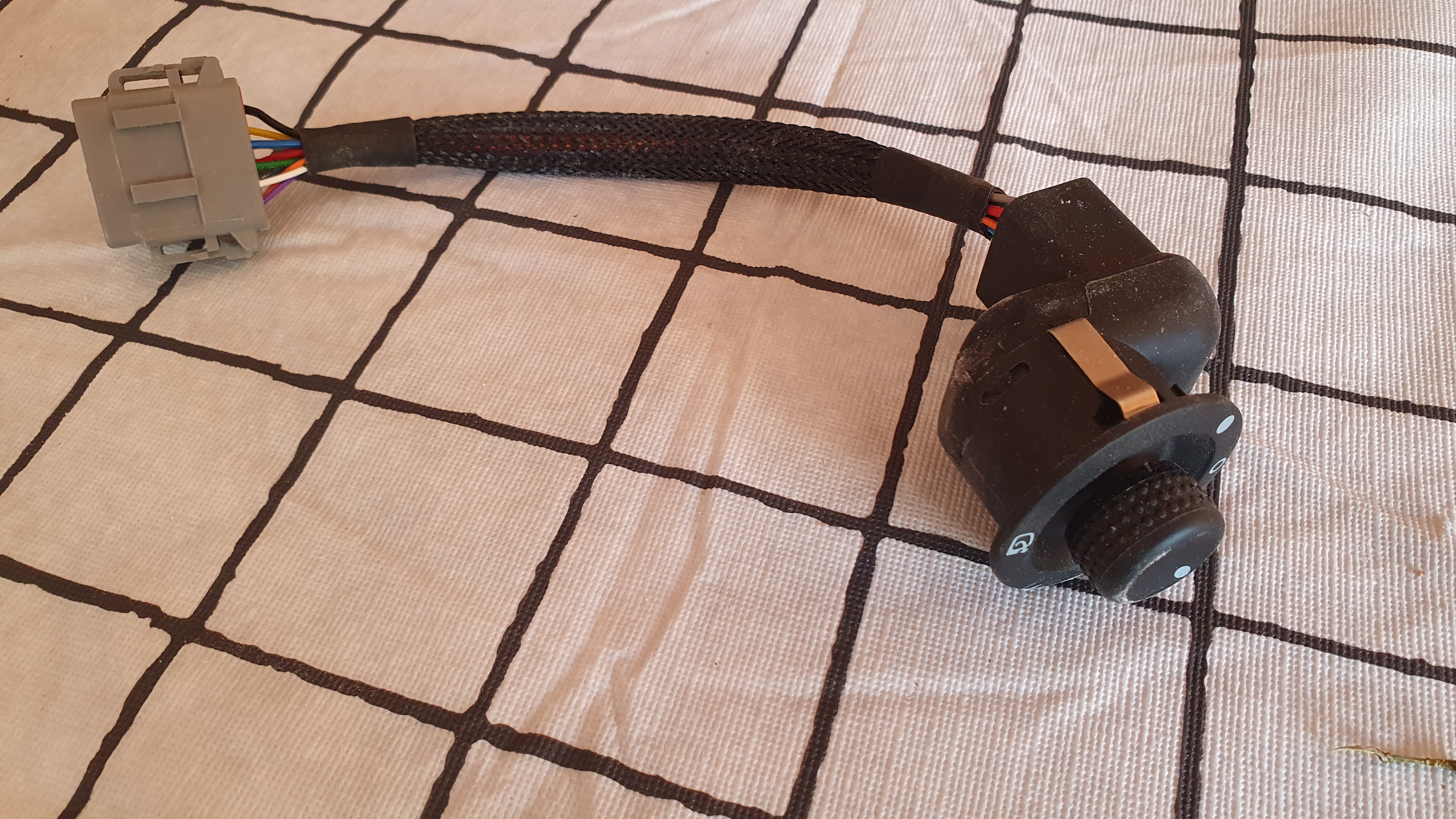
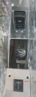
Some things just go right. The two yellow buttons,
that will be used to operate the indicators, by chance had internal lights that
will be set up to flash when the indicators are on. I also found that my
Forward, Neutral, Reverse selector had internal lights that light up the D,R,N.
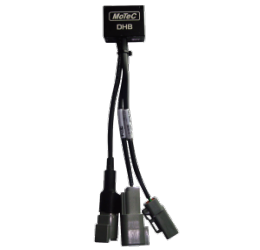
I installed a MoTeC (Duel Half Bridge) whatever that means, but in principle it
will send power to the linier actuator that operates the hand break, reversing
the polarity where necessary. When I started to wire up the DHC I noted that my
crimping tool was too small to crimp the male pins. On the basis that my tool
was too small I contacted Glen at
Auto Sports Electronics to see if he had a larger tool and sure he did. So I
took my male pins and wires to Glen, he got out his stripper then using his
larger tool did the job on my male pin.
It is good to know people who have
large tools who can help.
In addition to the wiring I have also modified the
dash to be able to install the radio, an item that is not standard in a Le Mans
car.
February 27 Week 17
Wiring of Switches, First Electrical Component Working. Better supplier of Deutsch plugs.
After a couple of weeks holiday and a week in Punishment
mode catching up with work I began to get on with the GT40E.
I have been
working predominantly on the wiring of the car. Some of the switches for example
the light selector for Head light / Auto / Off / Parking, have complex
electronics that are not easy to use in a kit car. They are just plug and play
into a more complex computerised car. My solution is to get the soldering iron
and strip out all of the components, then with some playing around with the
multi meter to find the connections to the plug and mechanical switch, then link
the two with a wire. See the photo below. Note some components have small led's
that you may want to use so strip the components with care.
I have wired most
of the switches on the dash board into the MoTeC system. Much of the mapping was
done on the bench, even before the car arrived so it was not too hard. Well
let's see when I try to get everything working.
The most simple component
was the horn with the power going from the battery, to a fuse box at the front
of the car, via the ignition switch. It was nice to see it fire up first try.
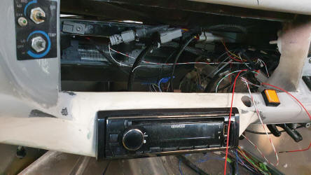
I recently purchased a radio / CD player and have started to cut out the
dashboard for its installation, see in the film below. There will be some
shaping of the original dash to make it fit and look suitable. Some people mount
their radio in the door, but it goes against the grain taking my eye off the
road and looking down to the right. Let's hope that the installation looks ok.
During the build of the car I have used many Deutsch connectors. These are great
components but if you buy from many of the suppliers like RS Components and
Element14 the components come separately Male, Female, Wedge Male, Wedge Female
and Male and Female pins. The aforementioned suppliers give no indication as to
the matching components and generally don't reply to the question "What goes
with what." Anyway I was delighted to be guided by Glen at
Auto Sports Electronics who
put me in touch with CTALS who supply
the whole kit or at least give you the matching components. They have my orders.

January 23 2022, Week 15 & 16
Install front Battery Box, Air Ducts, Wiring of
CANBus


 The
far left photo shows the orange battery box now in place. There had to be a
slight modification as it was originally designed to fit tight against the left
hand wall. When it was finally ready to fit into place I had an issue that the
height voltage cable exited the box on the far left side, so it no longer fitted.
A mod to the exit point allowed the original location to work as I bought the
cable out of the back of the box. But typically a 2 hour job turned into a 1 day
job. My time budget keeps extending. I was hoping to have the box fitted about a
month ago!
The
far left photo shows the orange battery box now in place. There had to be a
slight modification as it was originally designed to fit tight against the left
hand wall. When it was finally ready to fit into place I had an issue that the
height voltage cable exited the box on the far left side, so it no longer fitted.
A mod to the exit point allowed the original location to work as I bought the
cable out of the back of the box. But typically a 2 hour job turned into a 1 day
job. My time budget keeps extending. I was hoping to have the box fitted about a
month ago!
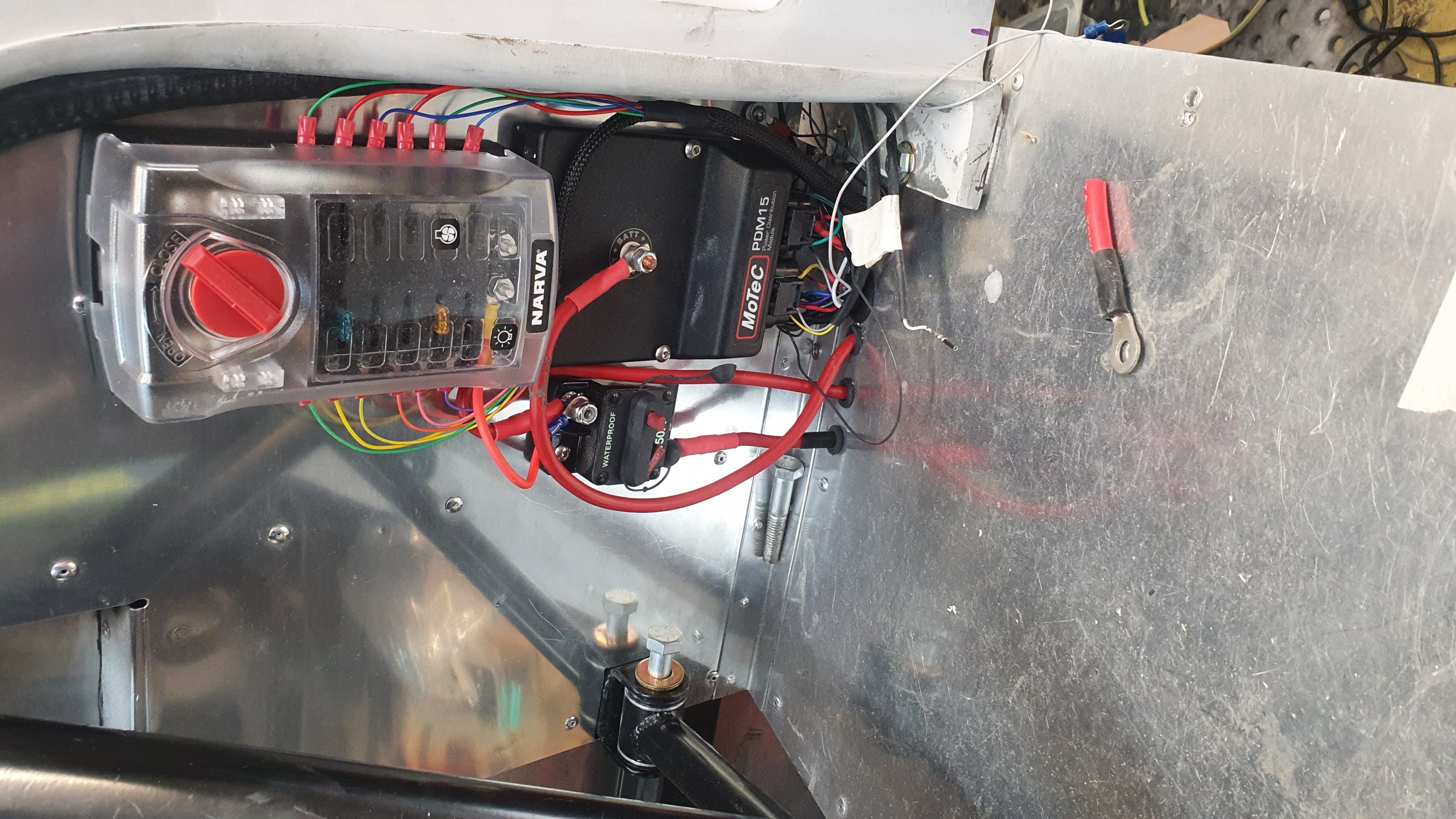
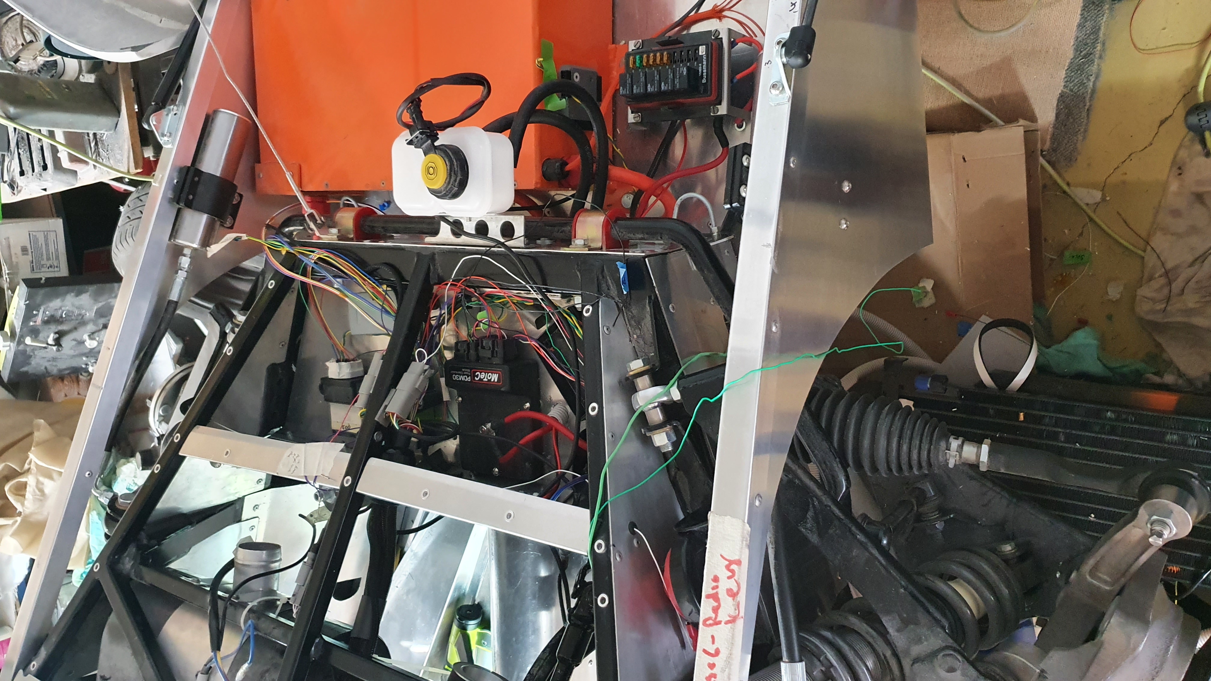
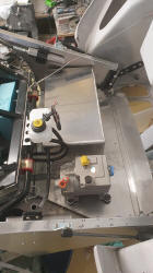
The front PDM (Power Distribution Module) and two CANBus switch
boxes are not in place. As shown in the same photo. The complete CANBus wiring
is completed and the dash board's wiring is nicely progressing. I have also been
continuing my work on the air-conditioning tubing that runs behind the
dashboard, a slow job with glass
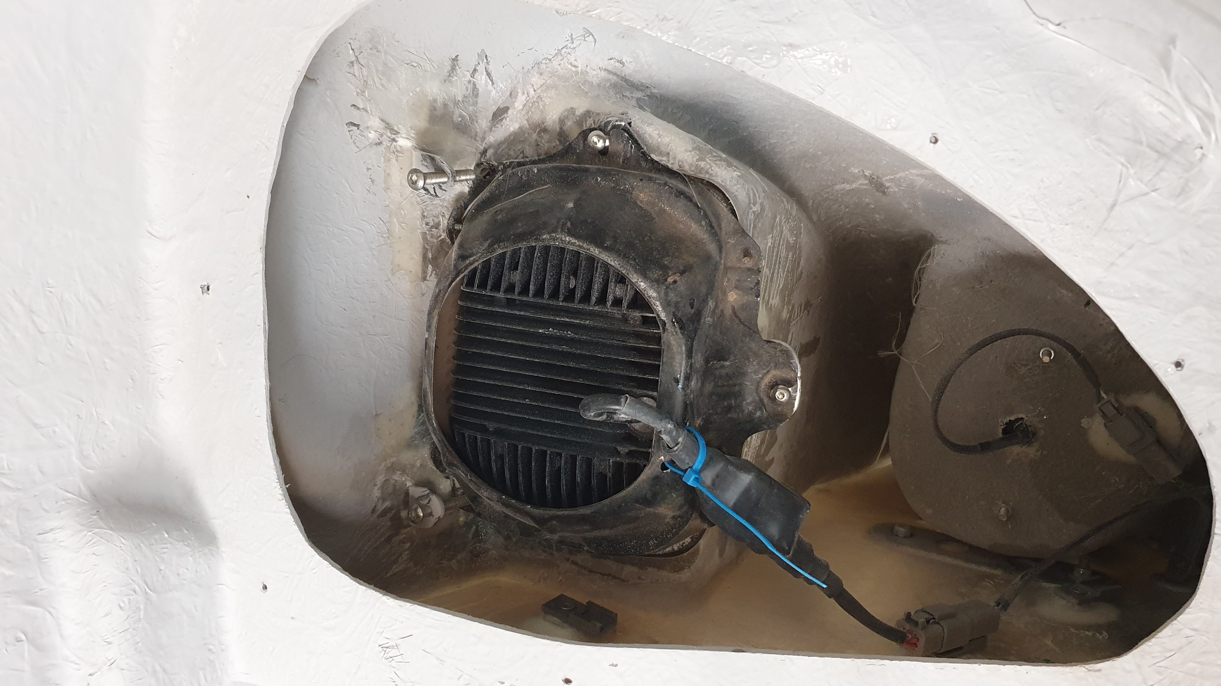
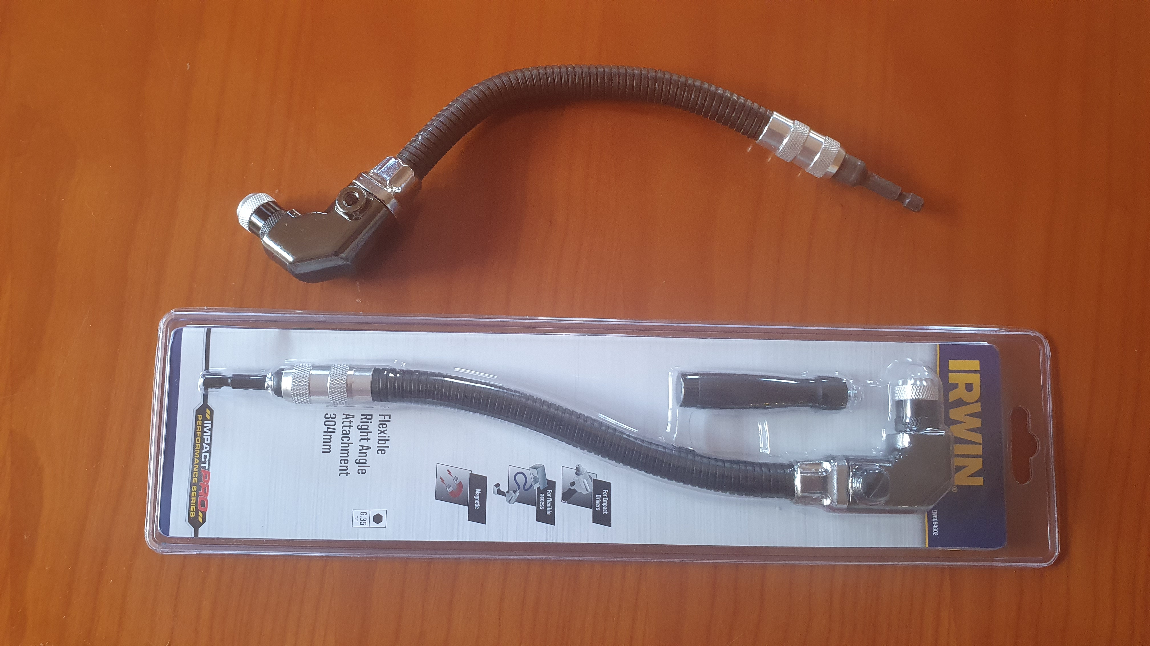
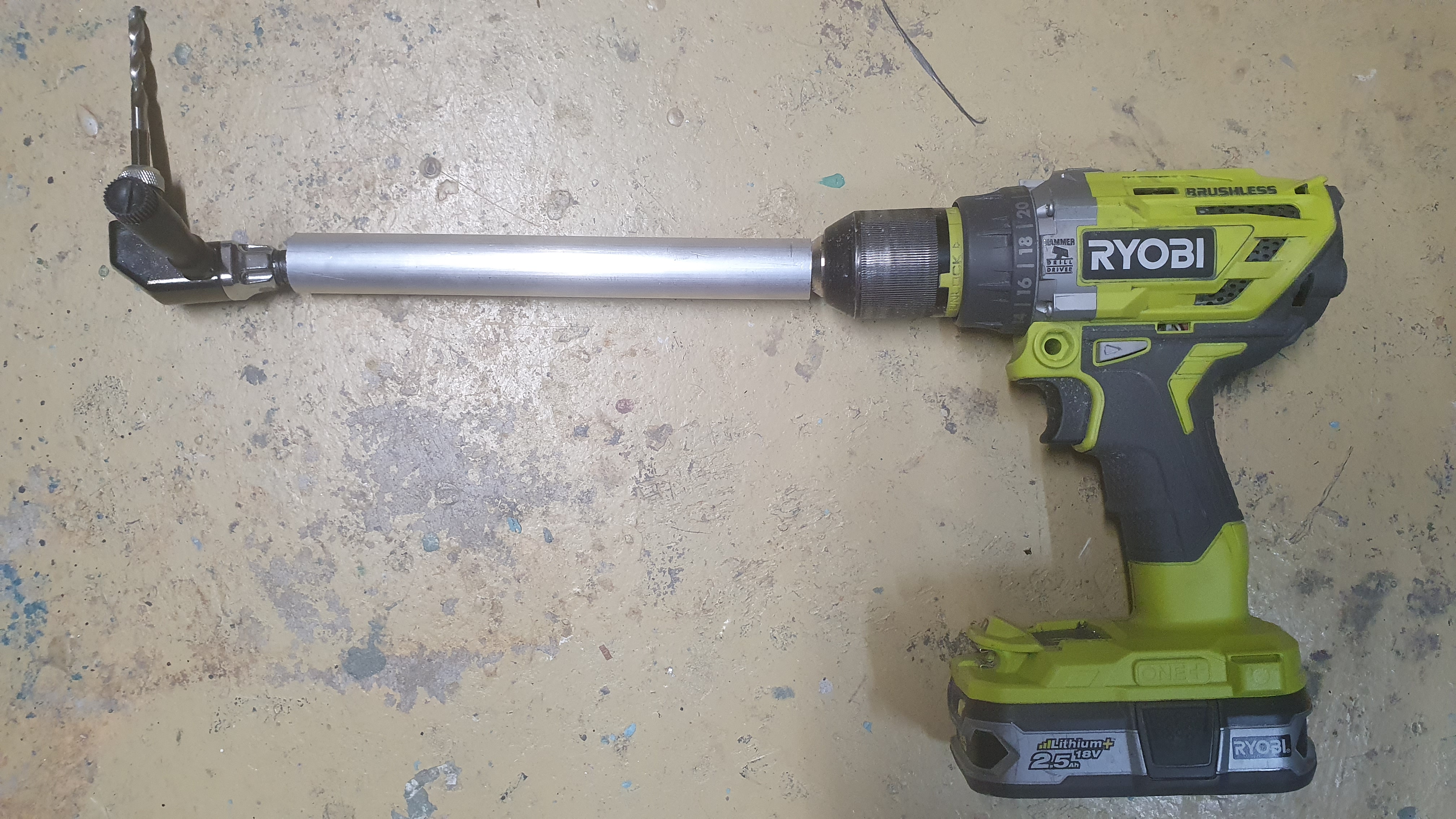
There is a great drill extension made by Irwin that allows you to drill into tight spots and around corners. I have found it so useful to get into tight spots. It works on a boden cable system with a flexible drive inside a flexible tube. Great until the drill bites, the whole cable twists and buckles making it useless. I have already been through two of these extensions. My fix is to buy an aluminum tube to go over the drive shaft when it is not critical. Otherwise gradually increase the drill bit size but I will see if the solution works for the future.
January 9 2022, Week 14
Further Prep of Dash board and other switch locations, Preparation of electronic hand break, Wiring of rear lights.

 A
little bit of work was done on the dash board, with the air con vents on the far
right and left completed. The light switch mounted. This however I could foresee
an issue of making a neat finish on the switch surround. Most of the circular
instruments have a chrome ring that hides the gap between the instrument and its
locating hole. After some Googling a chrome ring could not be found so I went to
the solution of what I am most happy building, by starting to make a Carbon
Fiber ring. This started with laying up a number of sheets of Carbon between
polyester sheet, that gives a nice finish. Note don't use polyester resin as it
is not colorless. Find a good supplier of epoxy and purchase clear resin. Let's
see how I progress.
A
little bit of work was done on the dash board, with the air con vents on the far
right and left completed. The light switch mounted. This however I could foresee
an issue of making a neat finish on the switch surround. Most of the circular
instruments have a chrome ring that hides the gap between the instrument and its
locating hole. After some Googling a chrome ring could not be found so I went to
the solution of what I am most happy building, by starting to make a Carbon
Fiber ring. This started with laying up a number of sheets of Carbon between
polyester sheet, that gives a nice finish. Note don't use polyester resin as it
is not colorless. Find a good supplier of epoxy and purchase clear resin. Let's
see how I progress.
I had purchased a second hand Commodore electronic
hand break actuator, but unlike other switches and wing mirrors I was unable to
figure out how the wiring worked, so I set to work using a standard actuator
that would be mounted between the drivers seat and the batteries in the right
sill. Drawings were made and sent toCadCut to make some
steel mounting brackets. I guess I will start on that in a couple of working
weeks.
Many jobs like the above don't get a tick of "Done" against them but I
finished wiring the rear lights, making sure that I maintained details of wire
colours, pin numbers from light to plugs and finally the PDM (Power Distribution
Module.) A good feeling of satisfaction to see that job completed. I little bit
of luck as the evening before I started the wiring and braiding I got an email
stating that my Mini Cooper reversing lights were on the way. I had completely
forgotten the reversing lights! So with that little reminder I was able to add a
wire to accommodate the reversing lights. (I believe there has to be a lot of
checking that everything is in place before the harness is completed.)
December 31 2021 Week 13
Preparation of Dash board switches.
 Now
it is time for a new phase of the build, that being mounting of the dash board's
switches. This has mentally taken a long time, with lists of what has to be
mounted to look good and ends up being practical. In the days of the GT40 and
similar cars like Jags, my dad had many Jaguars, there would be a line of
identical switches. It looked like an aircraft cockpit but had a fundamental
problem being that, as each switch was the same you had to take your eyes off
the road to work out what switch did which function. This caused many accidents.
I believe that the new Tesla electronic screen will have the same issues. This
in mind I am trying to make all the switches have obvious functions, look
different, but not cluttered. So there was lots of mental planning over the past
few months, and more recently, just sitting in the car working out where to
locate everything. Let's hope that I am right as once the switches are in place
and the upholstery fitted, there is a level of permanence.
Now
it is time for a new phase of the build, that being mounting of the dash board's
switches. This has mentally taken a long time, with lists of what has to be
mounted to look good and ends up being practical. In the days of the GT40 and
similar cars like Jags, my dad had many Jaguars, there would be a line of
identical switches. It looked like an aircraft cockpit but had a fundamental
problem being that, as each switch was the same you had to take your eyes off
the road to work out what switch did which function. This caused many accidents.
I believe that the new Tesla electronic screen will have the same issues. This
in mind I am trying to make all the switches have obvious functions, look
different, but not cluttered. So there was lots of mental planning over the past
few months, and more recently, just sitting in the car working out where to
locate everything. Let's hope that I am right as once the switches are in place
and the upholstery fitted, there is a level of permanence.
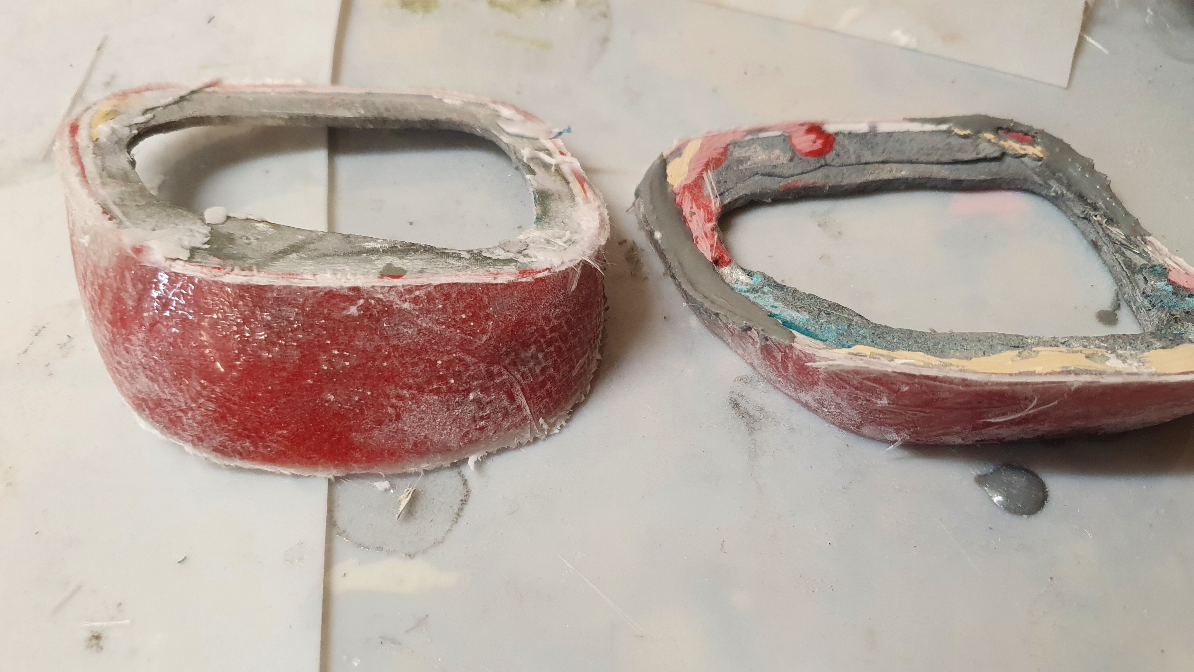
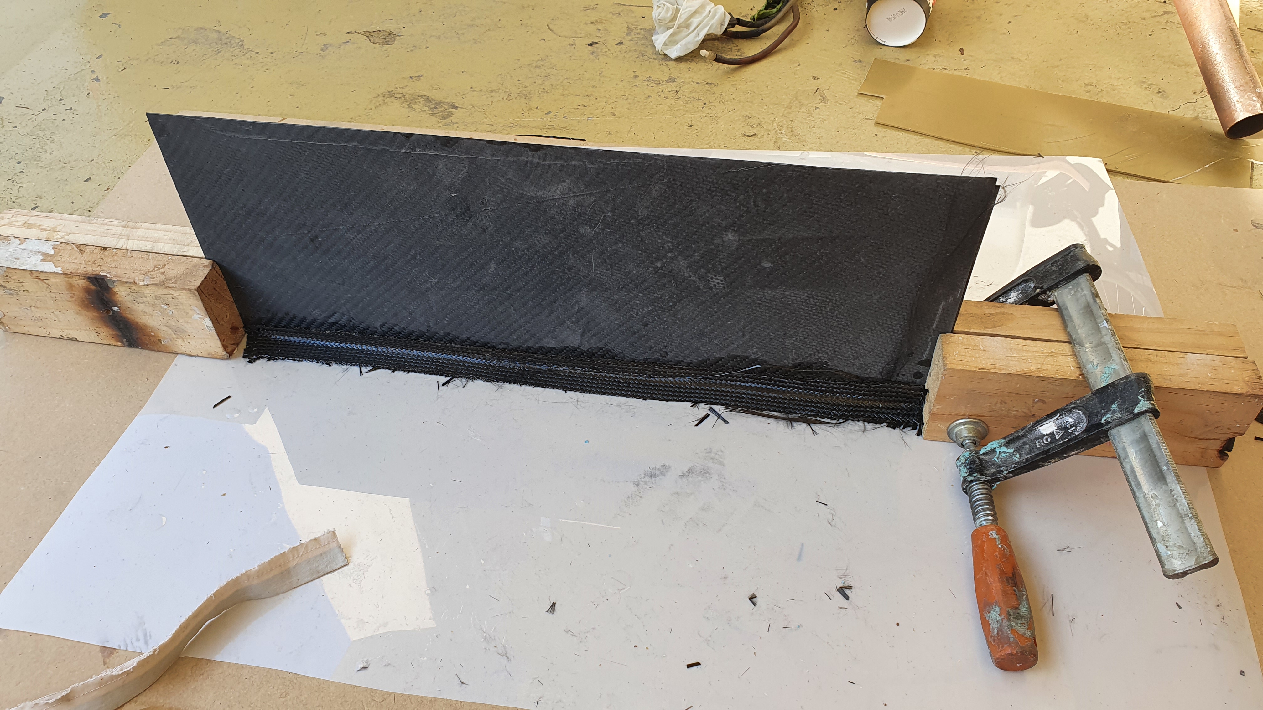
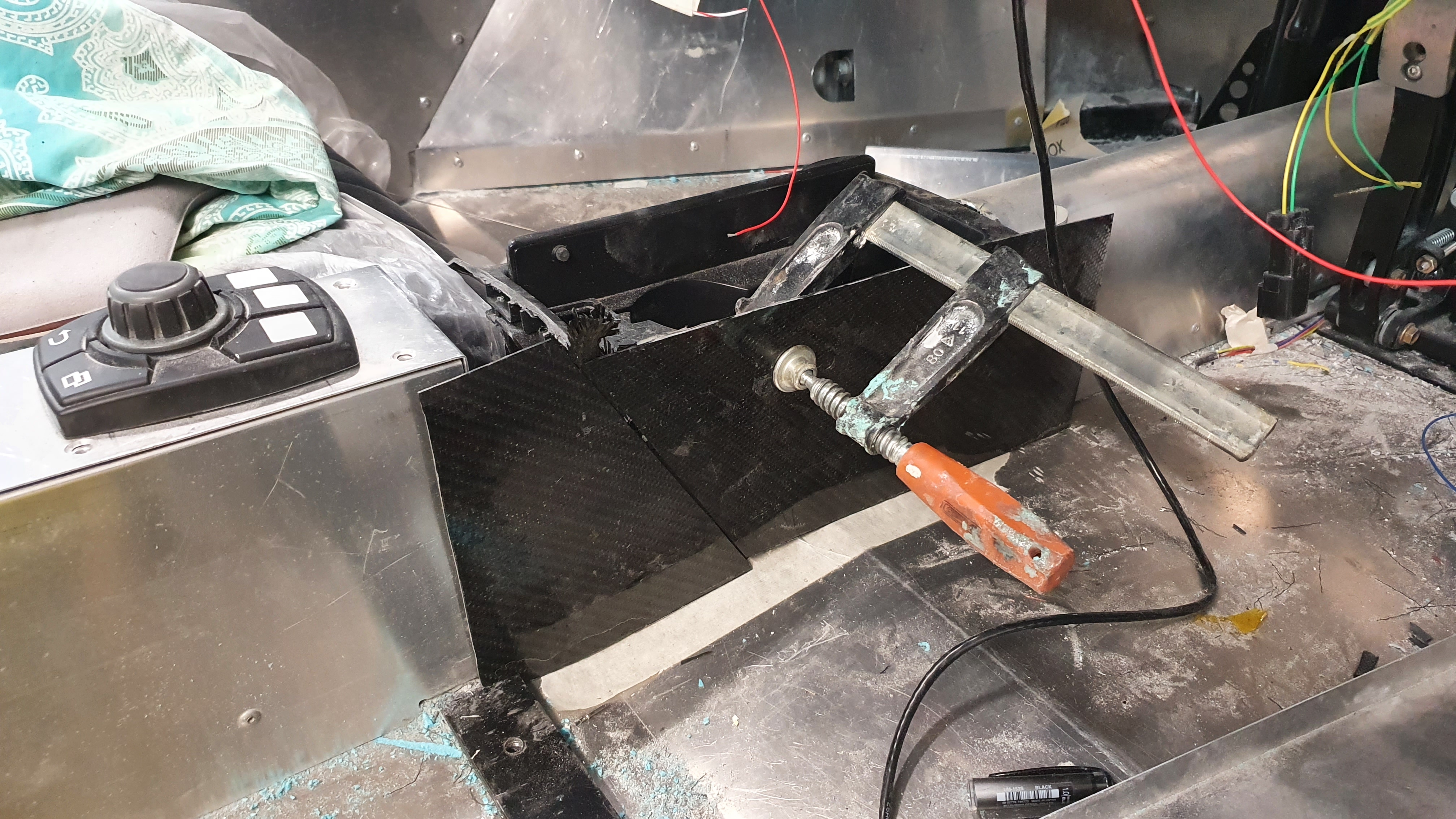
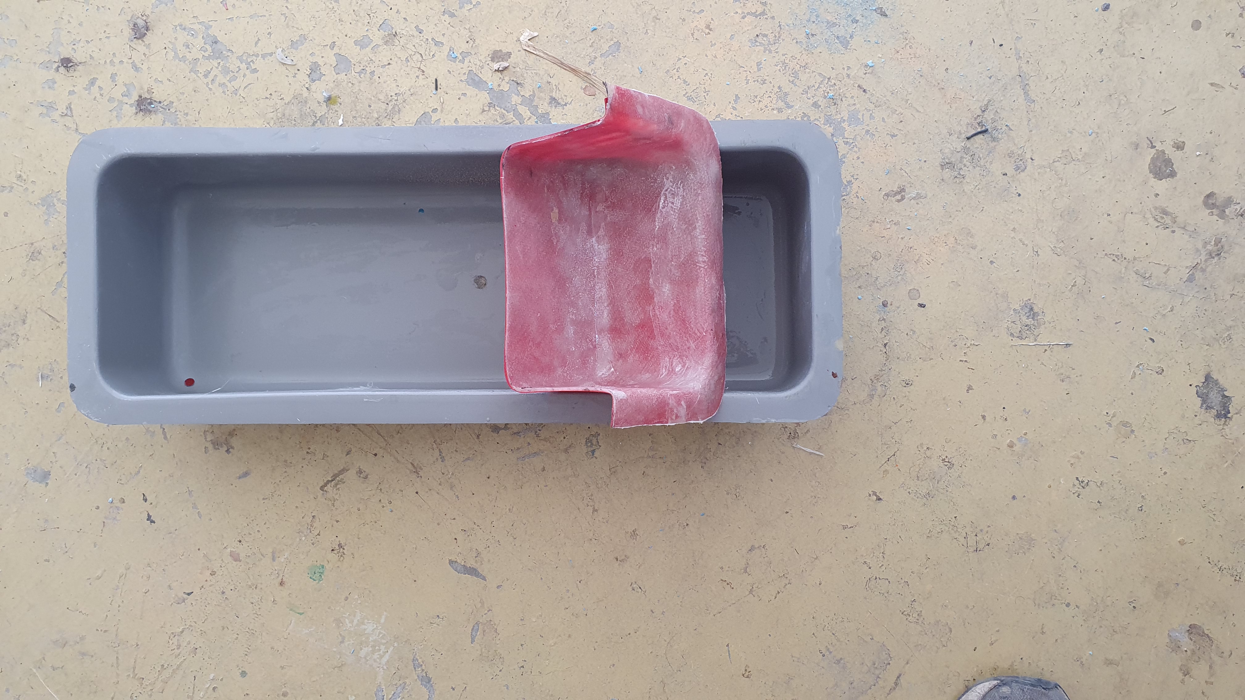
In addition to the face of the dash board i have been making a couple of glass fiber ducts for the air-conditioning vents on the far right and left of the dash. There is a very tight gap to the vents so some modifications are required, but as I have worked with glass since my early teens this is a job I feel comfortable with. No the photo is not the finished job, just their state as of Jan 1.
December 25 2021 Week 11 & 12
BMS harnesses for Sill Battery Boxes, Wiring of Tesla to temp switches.
Although two weeks have passed there are not so many photos to show progress.
The two side battery boxes have had their BMS wiring completed. I have then
stripped the batteries and wiring out in preparation for powder coating. In
addition the battery box that houses an additional 12 batteries in the front of
the car was completed, the BMS harness made and then stripped down ready for
powder coating. I have found that so many times components, just fit, the
grommets for the BMS and high voltage just squeeze next to each other in the
box, with no room to spare.
I was hoping to be completed the Tesla wiring before Christmas but time will often run faster
than I can work. Always double the time you expect. Tim fromEV Works spent a few
days connecting the Tesla's wiring. Initially I have a temporary switches that
will be replaced as the MoTeC system is installed. The MoTeC has already been
partially programmed on the desk, but switching across to the real thing will be
done step by step.
December 6 2021 Week 12
All Battery boxes installed but not all wired, BMS harness, Steering sensor.


Some weeks you feel that you have made much more progress
than others, despite the hours input into the project. This felt like a good
week.
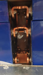
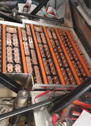
The second battery box was placed over the bottom box, filled with
batteries and copper connectors bolted in. Tim from EV Works
spent a day measuring up the high voltage cable to link up the different boxes,
Back Bottom, Back Top, Right and left sill and front. However at the early stage
of the build we will only use the Top back box and keep the voltage down whilst
we get used to the system. Much better to play with 30 volts rather than 300!
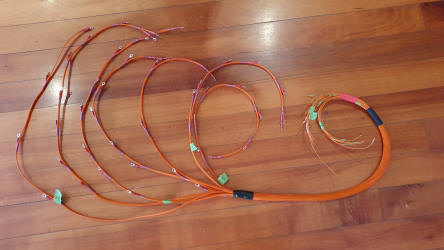
I spend quite some hours making a wiring harness for the Battery Management
System (BMS). This connects each copper connector in the bottom box and measures
the voltage difference. 48 individual wires! This harness will feed into the top
box where the brains of the system are located. So there needed to be a solution
to number each wire 1 to 48 so that they can be connected correctly. My
solution. Get some masking tape, wrap it over (not round) the end of the wire
and then tear it off. This will leave a tiny bit of tape on the wire. This can
then be marked with Dots and Dashes, a dash being 5 a dot being 1 so - - ... is
5 +5+1+1+1 = 13. When things get too tight i.e. 20 change the colour of the
tape.
I purchased a throttle sensor fromSmiths Racing Services
and mount from
Motor Sport Parts. Easy enough to mount other than the Tilton pedals are USA
made and use imperial Alan keys!
November 28 Week 10 & 11
Battery box. Steering wheel.

 Every
job takes far longer than you expect. Anyway the back battery box is now bolted
and in place, with the copper connectors fastened to their relevant battery, I
have started planning to wire in the Battery Management System (BMS) and attach
the braiding. This is not going to be as easy, as there are 48 wires that
go from each copper connector in the bottom box to the BMS in the top box. It
will be necessary to wire each one to the correct point in the BMS and then!
Take them all out when the car works, so that the boxes can be powder coated,
and the car sprayed. Then all reassembled in the right place.
Every
job takes far longer than you expect. Anyway the back battery box is now bolted
and in place, with the copper connectors fastened to their relevant battery, I
have started planning to wire in the Battery Management System (BMS) and attach
the braiding. This is not going to be as easy, as there are 48 wires that
go from each copper connector in the bottom box to the BMS in the top box. It
will be necessary to wire each one to the correct point in the BMS and then!
Take them all out when the car works, so that the boxes can be powder coated,
and the car sprayed. Then all reassembled in the right place.
I did run into
an issue on Friday, that being that I received a very light tingle from the
batteries. As I was only touching one bank I considered that there could have
been a short to earth. Testing the voltage from Earth to each copper connector,
it certainly appeared to be the case. However there should have been none! So a
lot of connectors came off just in case. Hopefully next week I should find the
reason for the short.
Be where not to short the copper plates. I did and only
had about 30 volts not 300!
Steering wheel in position.
November 14 2021 Week 8 & 9
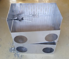
Battery boxes virtually completed. Motor installed with brace, Steering column decisions, Wing Mirrors progress. Fuel filler. Letter received from DoT


 The
main job over the past two weeks has been building the Battery boxes.CadCut completed the boxes some time
ago and the past two weeks my friend Sid Lacy, a glider pilot like me and a
talented welder, came for a number of afternoons and evenings to weld up the
battery boxes. By the end of this fortnight all the boxes were completed. Those
boxes to be fitted under the doors, there is a lot more room than a
standard car, were in place and a relatively small box was installed in the
front. The big boxes are still awaiting a Perspex cover to be made.
The
main job over the past two weeks has been building the Battery boxes.CadCut completed the boxes some time
ago and the past two weeks my friend Sid Lacy, a glider pilot like me and a
talented welder, came for a number of afternoons and evenings to weld up the
battery boxes. By the end of this fortnight all the boxes were completed. Those
boxes to be fitted under the doors, there is a lot more room than a
standard car, were in place and a relatively small box was installed in the
front. The big boxes are still awaiting a Perspex cover to be made.
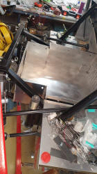
In
preparation for the installation of the large battery boxes, to be placed in the
rear of the car, crush tubes were welded in place. Crush tubes are inserted into
the 40 x 40 mm beams where a bolt will be placed. These tubes prevent the beam
being crushed when the bolt is tightened up.
Sid and I installed a brace of
the left side of the motor that will support the motor against the chassis, in
compression, whereas the initial installation was under tension.
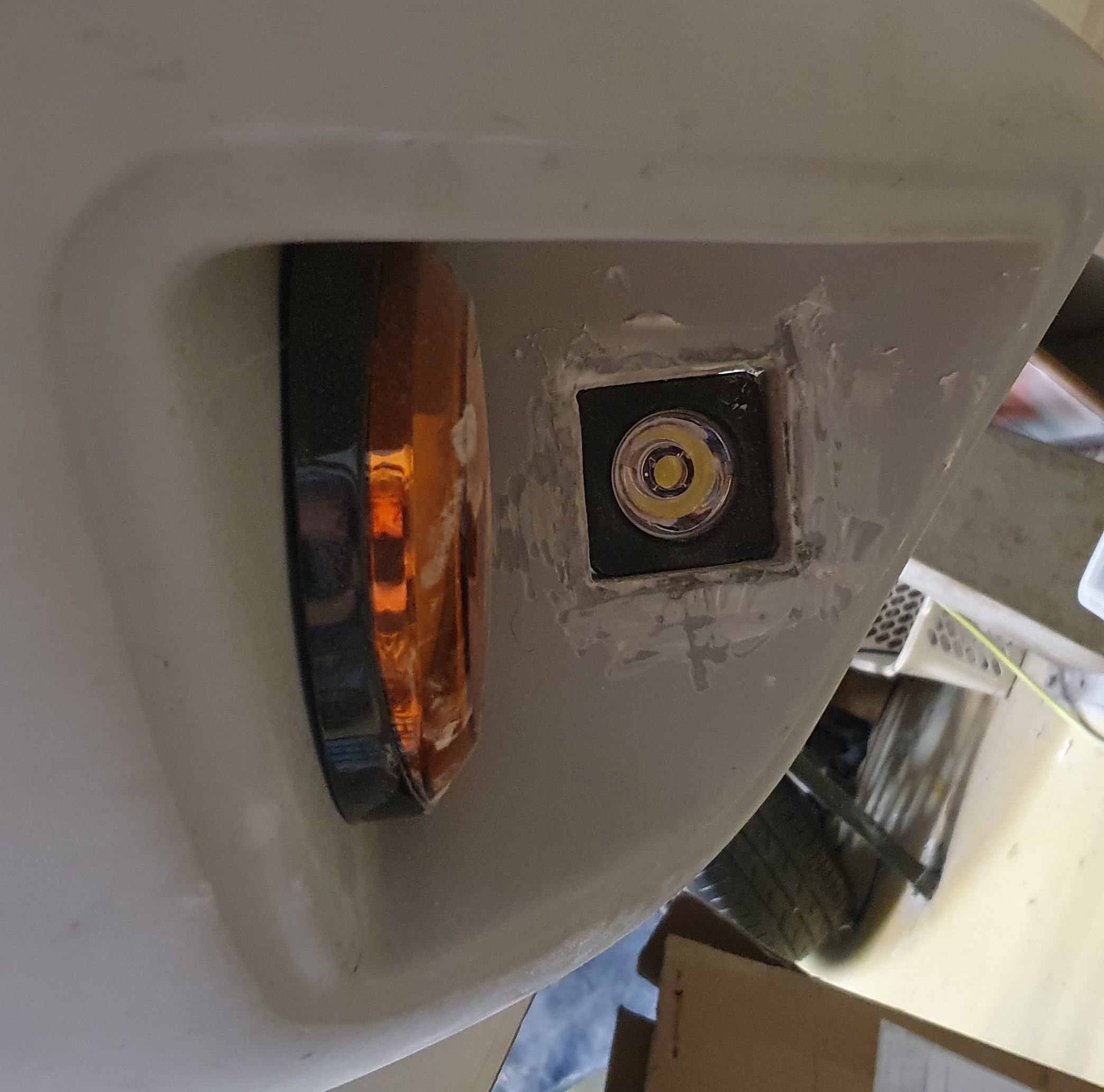
Lights,
Wipers and Indicators. It had been my intention to modernise the GT40 and
operate the lights, wipers etc. with stalks. However once I got to work with
assembly it became clear that this was not going to be possible, so I would have
to go to the traditional style of placing the switches on the dash. The next few
weeks I will hopefully start progress here, but good planning will be required.
I purchased from a scrap Audi RS3 wing mirror. By making test connections with
12v supply in all the combinations I was able to find out the function of each
wire, remember if you do this you may find as in the Audi reverse polarity
reverses direction i.e. up / down, left / right. Replacement covers are
available if yours is a little scratched.
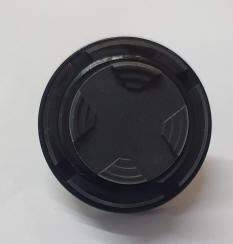
I recently received the delivery of
the fuel filler cap and charging plug. I was delighted to see that the two
components fitted like a glove. I wonder when they designed the GT40 in the 60's
if they were aware of the size of the charger plug size.
I also received this
week the confirmation from Department of Transport the ok to go ahead, together
with permission to work with my engineer on electric hand breaks.
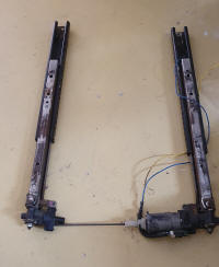
October 30 2021 Week 6 & 7
Drivers Seat installed. Tesla motor half installed. Wiring harness attachments made.
 The drivers seat was installed with motor driven rails. I
will not use the demonstrated switching system, I think something a little more
advanced is required. The fundamental issue was minimising the height added to
the seat by installing the rails.
The drivers seat was installed with motor driven rails. I
will not use the demonstrated switching system, I think something a little more
advanced is required. The fundamental issue was minimising the height added to
the seat by installing the rails.

 The Tesla motor was put back into the car,
but I had a concern that the motor is particularly heavy on the rotor side so a
stiffening beam, that will be under compression, is being made to support the
weight in addition to the frame that is located above the motor where it will
hang. Hopefully this will be completed next week and photos will indicate the
modification.
The Tesla motor was put back into the car,
but I had a concern that the motor is particularly heavy on the rotor side so a
stiffening beam, that will be under compression, is being made to support the
weight in addition to the frame that is located above the motor where it will
hang. Hopefully this will be completed next week and photos will indicate the
modification.
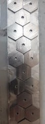
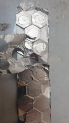
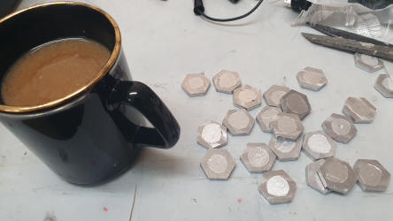
It is necessary to secure the wiring harness to the glass fiber
body in some places. My solution is as follows:-
I hadCadCut, who
cut my battery boxes, make about 50 hexagonal pieces out of 4mm aluminum.
Hexagons as they are economic to cut and they don't rotate under the glass. Each
had a 3mm hole in the center that I eventually drilled and tapped to suit a 4mm
thread.
I then taped over the pieces some silver tape, that can be purchased
from any good glass fiber supply. The reason for this is that the tape will
prevent resin egressing into the tapped hole.
The Hexagons were then glassed
onto the body work. Using a counter sunk drill the glass was pierced allowing
the 4mm screw to secure either the Deautch plug attachments or tie clips.
Yes
the whole area will be cleaned up.
 The
battery boxes for the rear of the car are virtually finished with the help of my
friend Sid, who is a first class welder. I certainly learnt that drawing up
components in a 2D sketch does not guarantee that they fit into a 3D car, but
with a little modification the boxes were moved into position.
The
battery boxes for the rear of the car are virtually finished with the help of my
friend Sid, who is a first class welder. I certainly learnt that drawing up
components in a 2D sketch does not guarantee that they fit into a 3D car, but
with a little modification the boxes were moved into position.
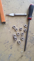
The battery
beams were finished and square bolts inserted into each end. They are a tight
fit and with a hard tap on the end with a cold chisel they were secured. I
obtained my nuts fromBolt & Nut
Australia, who had my goods delivered within a few days of order.
It was
necessary to file a little inside the beams to make the nuts fit.
The right
hand photo shows the bottom battery box in place, but not secured yet.
I
expect some batteries to be installed and wired within a couple of weeks.
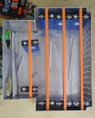
October 16 2021 Week 4 & 5
Steel beams coated with glass, Aircon fitted, Anti theft ordered, break line modified, battery boxes collected.
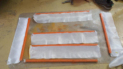
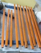
I have combined two weeks of work in one session as I felt that I had not done much work, and was too busy on the weekend to write a report, but looking back it looks as if some progress has been made. Firstly I have virtually finished completing the steel beams that hold the batteries down in the battery boxes. Critically the beams need to be covered in glass fiber to insulate them from possible electrical shorts. In addition as High Voltage wiring are required to be Orange, I will go the whole hog and paint high voltage components as well. Well not the motor. A note in applying the glass, tack the glass into place first, then when the resin has cured wrap it. I then coded with a layer of epoxy (as it is less viscose than polyester, and leaves a nice smooth surface. A final coat of orange will then take place.
A lot of time was spent on installing the Air-Conditioning. I drilled the two holes in the underside of the demister as per the photo in the instruction manual, only to find that some beams of the chassis interfered , so the holes were glassed up and new pipe manifold positions found, drilled and manifolds re fitted. Getting the air-conditioning unit in the right place required it to be located, marked, removed, drilled and and and and. I think it must have been put in and out of position about 6 times.
The break lines were removed and marked for new ones to
be made, as battery boxes will be fitted in the sills where they are located.
The Anti Theft device was purchased and arrived.
Finally
the battery boxes and battery contacts arrived fromCadCut in Wangara. It
has taken some time but the present economic climate everybody appears to be
very busy. Hopefully next week I will see some good progress with my friend Sid
able to help me with aluminum welding of the boxes and the seat rails.
September 30 2021 Week 3
 Although this is a few weeks after week 2 it is because we went away in the
Motor Home for a couple of weeks, resting after runningPing-Pong-A-Thon, a
charity event we are involved with. We support charities that fight against
slavery, watch this.
Although this is a few weeks after week 2 it is because we went away in the
Motor Home for a couple of weeks, resting after runningPing-Pong-A-Thon, a
charity event we are involved with. We support charities that fight against
slavery, watch this.
I have continued to work on the installation of the MoTeC display, as with
all fiber glass jobs it can take time, with one piece being glassed into place,
then wait for it to dry firmly before proceeding to the next step. I should be
finished next week.
I came to the realisation that guaranteeing, when the car
is finished I will have all the knobs and switches installed, and in the correct
location is not a guarantee. For example I could get to the point when all is
done that the switch to alter the climate's fan is not installed. My solution is
to make a menu in the MoTeC that all functions can be located and added and
modified.
Landsdale wreckers sold me a Lexus seat $100 so I could strip out
the seat rails. Hours of grinding took place to get rid of the excess metal
work. You have to remember that the seats need to be as close to the floor as
possible, other wise my head will rub against the roof.
The drive shaft
stumps arrived, very promptly, see video. I thought they were a bit expensive,
like the Hylux headlights I bought 2 pairs! Fortunately I already have a buyer
for the extras.
Now the Exciting bit. Time fromEV Works came on the
30th and ran the Tesla Motor. Much delight as I was always concerned that the
EBay purchased motor may not work.
September 3 2021 Week 2
 I
ordered drive shaft stump from
Zero-ev, in the UK as my Tesla motor did not come with the drive cups.
I
ordered drive shaft stump from
Zero-ev, in the UK as my Tesla motor did not come with the drive cups.
I
visited Sam Rossi, who will be my engineer overseeing the build. I was in the
process of making a Glass RSJ to hold the batteries down. I would make one and
hang some weights on it to test its ability to do the job. Sam put the
dimensions through his computer and came up with a figure well short of the
requirement, but quickly stated that a 20 x 20 steel beam 1.6mm would do the
trick if wrapped in glass to insulate. Good advice to keep all receipts and
packing for lights and ensuring they comply with Australian Design Regulations
before purchase. Great to work with people who know their job.
Tim, having
installed the replacement power board in the Tesla after half a days work
eventually managed to get the motor turning - Backwards. So he went away to test
the power board on his motor in his workshop.
I set to work drilling holes in
the dashboard for the Speedo, Volt meter and clock, all in 1960's style. The
grinder got to work cutting out a hole foot the MoTeC display. As I have worked
with fiberglass since I was about 14 I feel quite confident getting stuck in
here. If you make a mistake you can always patch it up.
Finding various parts
appears to fill half my time. Lights, switches, gas struts, and there will be far
more.